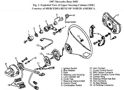
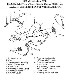
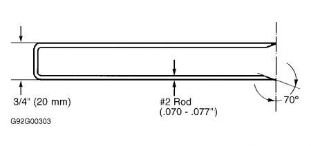
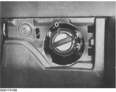
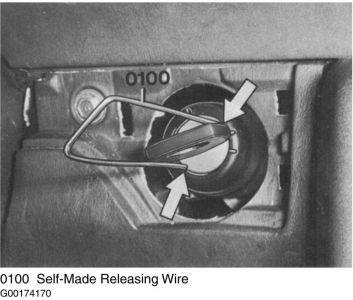
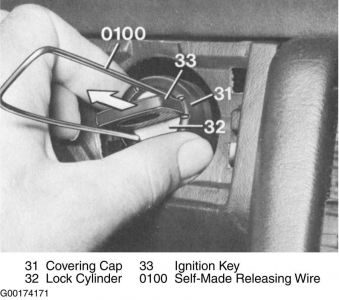
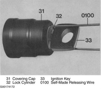
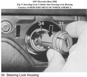
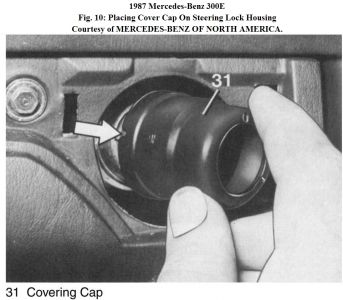
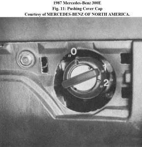
IGNITION SWITCH & STEERING LOCK HOUSING Removal & Installation Removal 1. Remove lower instrument panel cover below steering wheel. Remove snap-in panel around ignition key cylinder. Make reassembly reference marks on all wiring connectors. Disconnect wiring connectors from steering lock housing and from rear of ignition switch. Turn ignition key to No. 1 position. 2. Loosen steering lock housing retaining clamp bolt located near steering column. See Fig. 1 or Fig. 2 . Push in locking pin located to left of retaining clamp on jacket tubing. See Fig. 2 . Leave retaining clamp on jacket tubing. Pull steering lock housing out of jacket tubing slightly. 3. Remove ignition key to enable removal of steering lock housing from jacket tubing. With steering lock housing removed from jacket tubing, ignition switch can now be removed from rear of steering lock housing by removing 3 retaining screws. Installation 1. To install, locate ignition switch locating lug to recess in rear of steering lock housing. Install switch retaining screws. Ensure proper operation of steering lock and ignition switch mechanisms. Install steering lock housing into jacket tubing by pushing inward on housing locking pin and pushing steering lock housing into jacket tubing until bottomed. 2. Ignition key may require turning to engage steering lock housing locking tab into steering column. Ensure steering lock housing locking pin engages in jacket housing hole. Install clamp. Reconnect wiring connectors. Install lower instrument panel cover below steering wheel and snap-in panel around ignition key cylinder. LOCK CYLINDER Removal 1. Fabricate a releasing tool according to specifications. See Fig. 3 . Remove snap-in panel around ignition key cylinder. See Fig. 4 . Insert ignition key and turn to position No. 1. See Fig. 5 . Insert self-made releasing wire tool into both small holes in lock cylinder face. Small holes in lock cylinder face should be at approximately 1:00 and 7:00 o'clock positions with ignition key in No. 1 position. See Fig. 6 . Fig. 3: Fabricating Lock Cylinder Releasing Tool Courtesy of MERCEDES-BENZ OF NORTH AMERICA. Fig. 4: Removing Snap In Panel Around Ignition Key Cylinder Courtesy of MERCEDES-BENZ OF NORTH AMERICA. Fig. 5: Turning Ignition Key To Position No. 1 Courtesy of MERCEDES-BENZ OF NORTH AMERICA. Fig. 6: Inserting Releasing Tool Into Lock Cylinder Face Courtesy of MERCEDES-BENZ OF NORTH AMERICA. 2. Push inward lightly on releasing tool to unlock detents while pulling outward on ignition key to remove lock cylinder and cylinder cover cap from steering lock housing. See Fig. 7 . Remove releasing wire tool, ignition key and cover cap from lock cylinder. See Fig. 8 . Fig. 7: Removing Lock Cylinder & Cover Cap From Steering Lock Housing Courtesy of MERCEDES-BENZ OF NORTH AMERICA. Fig. 8: Removing Releasing Tool, Ignition Key & Cover Cap From Lock Cylinder Courtesy of MERCEDES-BENZ OF NORTH AMERICA. Installation 1. Align lock cylinder's raised guide area with steering lock housing groove. See Fig. 9 . Insert, but DO NOT bottom NEW lock cylinder into steering lock housing. Push cylinder cover cap onto steering lock housing with the small notch on cover cap's large diameter end, to the left side of steering lock housing. See Fig. 1 or Fig. 2 and Fig. 10 . Fig. 9: Inserting Lock Cylinder Into Steering Lock Housing Courtesy of MERCEDES-BENZ OF NORTH AMERICA. Fig. 10: Placing Cover Cap On Steering Lock Housing Courtesy of MERCEDES-BENZ OF NORTH AMERICA. 2. Insert ignition key and turn lock cylinder to No. 1 position. Push cover cap and lock cylinder into steering lock housing, ensuring both parts engage securely into steering lock housing. See Fig. 11 . Fig. 11: Pushing Cover Cap & Locking Cylinder Into Steering Lock Housing Courtesy of MERCEDES-BENZ OF NORTH AMERICA. 3. All parts are installed correctly if ignition key points to center indent mark (No. 1 position) on cylinder cover cap, and cover cap's large diameter end's small notch is aligned with raised portion on steering lock housing. Ensure proper operation of steering lock and ignition switch mechanisms. Install snap-in panel around ignition key cylinder.
Sunday, May 23rd, 2010 AT 9:32 AM


