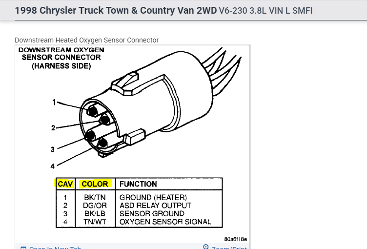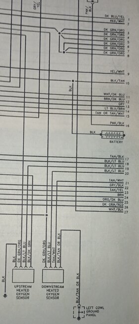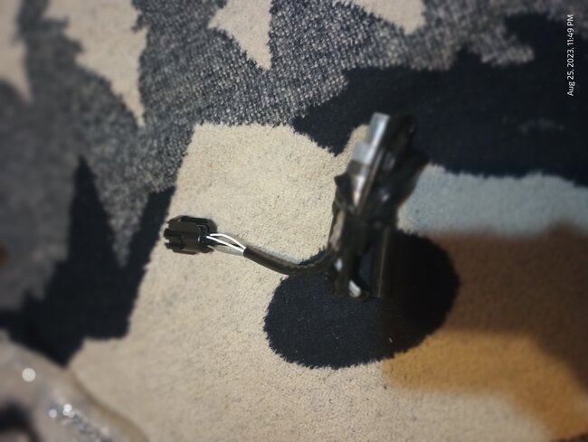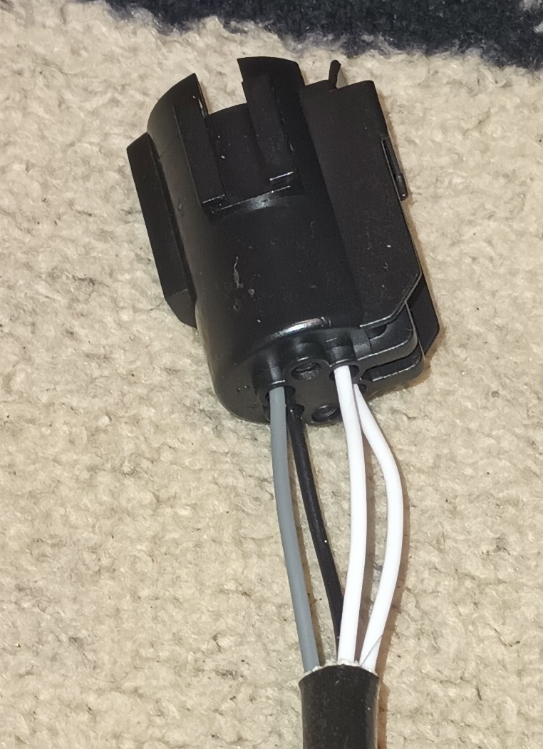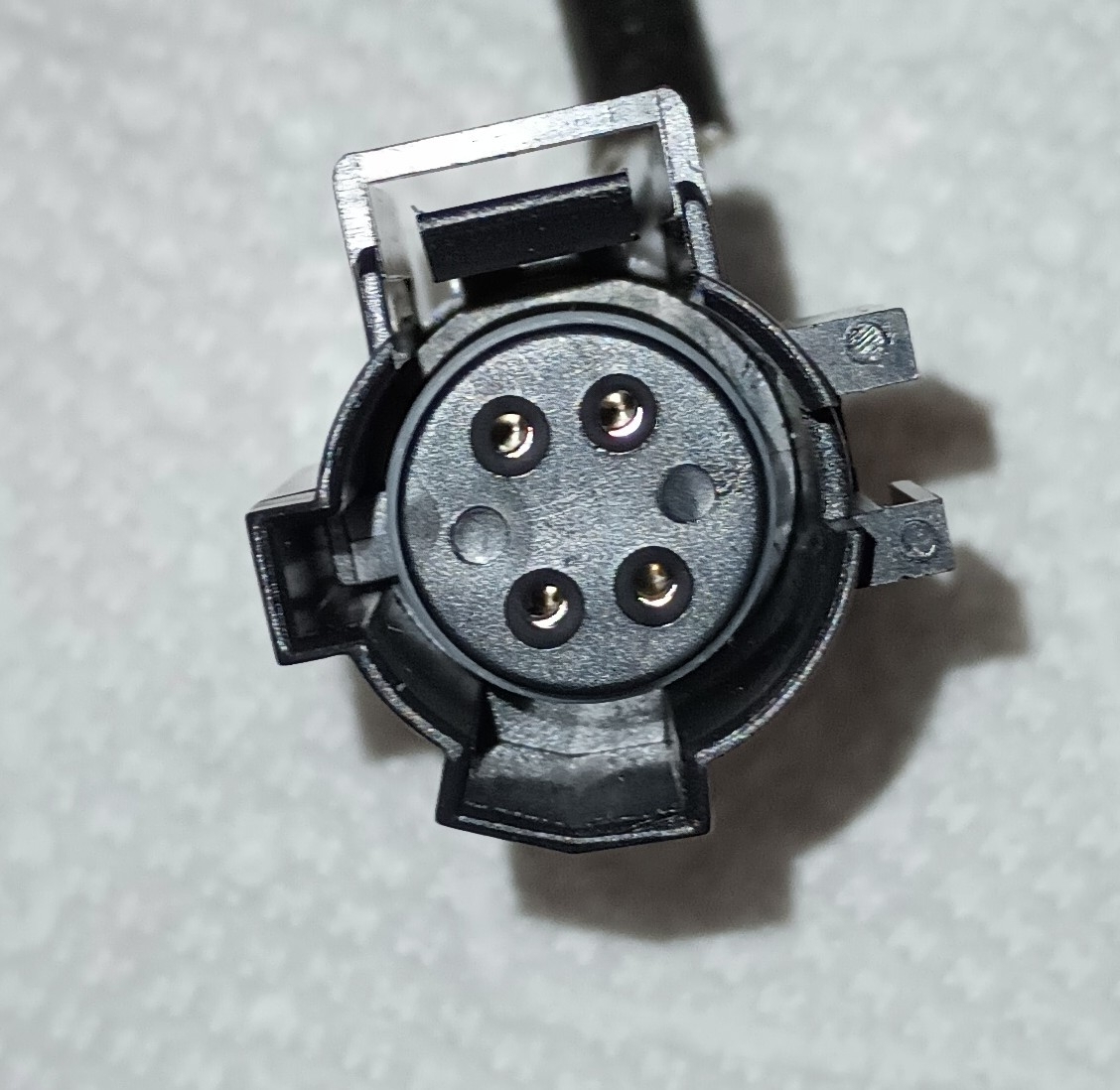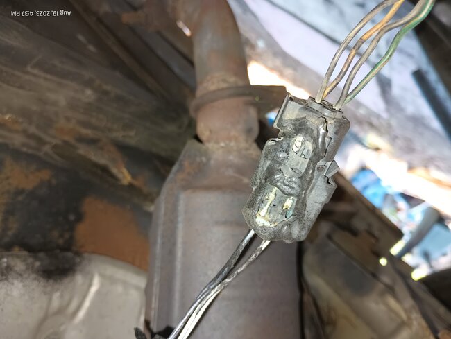
The downstream Oxygen Sensor melted together when I went to change the sensor. The problem is I can't see the vehicle side connection clearly enough to determine what wire goes where and connects to what wire on the sensor wire harness. I bought a replacement repair kit, STANDARD S-1933, which matches the OE kit 05013971AA to repair the connector.
Question,
Do any of your mechanics have a manufacturer schematic showing the connection setup?
My schematic (Haynes) only shows the vehicle side but does not show the connection to the oxygen sensor. Had this happen once before on a 1998 dodge grand caravan but on the upstream o² when it contacted the manifold. Fortunately, then the vehicle side was viewable enough to get the wires in place. The sensor wires are as follows: 2 white, 1 black, 1 gray. I know there are 2 grounds (body ground and sensor ground), 1 sensor power, 1 other positive but have no clue what connection goes where. I need help on this, and this a disability vehicle has to get exhaust pipes welded too so everything is getting done at one time in the outdoors (no shop here) setting.
Question,
Do any of your mechanics have a manufacturer schematic showing the connection setup?
My schematic (Haynes) only shows the vehicle side but does not show the connection to the oxygen sensor. Had this happen once before on a 1998 dodge grand caravan but on the upstream o² when it contacted the manifold. Fortunately, then the vehicle side was viewable enough to get the wires in place. The sensor wires are as follows: 2 white, 1 black, 1 gray. I know there are 2 grounds (body ground and sensor ground), 1 sensor power, 1 other positive but have no clue what connection goes where. I need help on this, and this a disability vehicle has to get exhaust pipes welded too so everything is getting done at one time in the outdoors (no shop here) setting.
Aug 25, 2023 at 3:19 AM