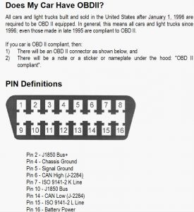
Using ohmmeter, check continuity between ground and terminals No. 4 and 5 on DLC. Continuity should exist. Repair as needed. Using voltmeter, measure voltage between ground and terminal No. 16 on DLC. Battery voltage should exist. If battery voltage is not present, inspect fuse No. 17 in Power Distribution Center (PDC). Replace as needed. If battery voltage is present, replace scan tool cable or scan tool as necessary. 1.Disconnect scan tool. Using an external voltmeter, measure voltage between ground and DLC terminal No. 3 (Violet/Brown wire). If voltage is not 2.3-2.6 volts, go to step 3) . If voltage is 2.3-2.6 volts, go to next step. 2.Measure voltage between ground and DLC terminal No. 11 (White/Black wire). If voltage is not 2.3-2.6 volts, go to next step. If voltage is 2.3-2.6 volts, replace scan tool cable or scan tool. 3.Disconnect instrument cluster connectors. Connect jumper wire between ground and terminal No. 3 (White/Black wire) on DLC connector. Using external ohmmeter, measure resistance between ground and terminal No. 2 (Violet/Brown wire) on right instrument cluster connector. If resistance is less than 5 ohms, go to next step. If resistance is 5 ohms or greater, repair open Violet/Brown wire. 4.Remove and inspect fuse No. 10. If fuse is open, go to next step. If fuse is okay, go to step 6) . 5.Turn ignition off. Remove fuse block fuse No. 10. Using ohmmeter, measure resistance between ground and fused ignition switch output terminal (Dark Blue/White wire) on fuse block fuse No. 10. If resistance is 5 ohms or greater, replace fuse. If resistance is less than 5 ohms, repair Dark Blue/White wire for short to ground. Replace fuse No. 9. 6.Remove instrument cluster. Turn ignition on. Using external voltmeter, measure voltage between ground and terminal No. 8 (Dark Blue/White wire) on left instrument cluster harness connector. If voltage is 10 volts or less, repair open Dark Blue/White wire. If voltage is greater than 10 volts, go to next step. 7.Using external ohmmeter, measure resistance between ground and terminal No. 6 (Black/Light Green wire) on left instrument cluster connector. If resistance is less than 5 ohms, go to next step. If resistance is 5 ohms or greater, repair open Black/Light Green wire. 8.Connect jumper wire between ground and terminal No. 11 (White/Black wire) on DLC connector. Using external ohmmeter, measure resistance between ground and terminal No. 1 (White/Black wire) on right instrument cluster connector. If resistance is less than 5 ohms, go to next step. If resistance is 5 ohms or greater, repair open White/Black wire. 9.Disconnect jumper wire. Measure resistance between ground and terminal No. 1 (White/Black wire) on right instrument cluster connector. If resistance is less than 1000 ohms, repair White/Black wire for short to ground. If resistance is 1000 ohms or greater, go to next step. 10.Disconnect jumper wire. Measure resistance between ground and terminal No. 2 (Violet/Brown wire) on right instrument cluster connector. If resistance is less than 1000 ohms, repair Violet/Brown wire for short to ground. If resistance is 1000 ohms or greater, replace instrument cluster.

Friday, April 23rd, 2010 AT 3:07 PM


