Hello
Do the following checks
POWER LIFTGATE RELEASE SYSTEM
Check fuse No. 8 in junction block. Junction block is located on steering column support bracket. If fuse is okay, reinstall fuse and go to next step. If fuse is blown, use wiring diagram as a guide to check for cause of blown fuse and repair as necessary. See WIRING DIAGRAMS. Replace fuse and recheck system operation.
Using a voltmeter, measure voltage between ground and fuse No. 8 connector, B+ circuit terminal (Pink/White wire). If battery voltage is not present, repair open B+ circuit between Power Distribution Center (PDC) and junction block. If battery voltage is present, go to next step.
Remove liftgate trim panel. See LIFTGATE TRIM PANEL under REMOVAL & INSTALLATION. Disconnect liftgate flip-up push button switch 2-pin connector. Using voltmeter, check voltage between ground and liftgate flip-up push button switch 2-pin connector terminal No. 2, fused B+ circuit (Pink wire). If battery voltage is not present, repair open B+ circuit between junction block and liftgate flip-up push button switch 2-pin connector. If battery voltage is present, reconnect liftgate flip-up push button switch 2-pin connector and go to next step.
Press liftgate flip-up push button switch. Using voltmeter connected to ground, backprobe liftgate flip-up push button switch 2-pin connector terminal No. 1, liftgate flip-up push button switch output circuit (Orange/Pink wire). If voltage is not present, replace liftgate flip-up push button switch. If voltage is present, leave liftgate flip-up push button switch pressed and go to next step.
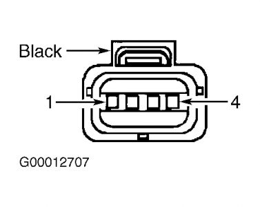
Disconnect liftgate lock motor connector. Liftgate lock motor is integral to liftgate latch mechanism. Using a voltmeter, check voltage between ground and liftgate lock motor connector terminal No. 3, liftgate flip-up push button switch output circuit (Orange/Pink wire). See Fig. 1. If battery voltage is not present, repair open liftgate flip-up push button switch output circuit. If battery voltage is present, release liftgate flip-up push button switch and go to next step.
Fig. 1: Identifying Liftgate Lock Motor Connector Terminals

Using an ohmmeter, check for continuity across liftgate lock motor (limit switch) terminals No. 3, liftgate flip-up push button switch output circuit (Orange/Pink wire) and No. 4, liftgate glass limit switch output circuit (Orange/Brown wire). With liftgate latch unlocked, continuity should exist. With liftgate latch locked, continuity should not exist. If continuity is not as specified, replace liftgate lock motor. If continuity is as specified, reconnect liftgate lock motor connector and go to next step.
Disconnect liftgate flip-up release solenoid 2-pin connector. Using an ohmmeter, check for continuity between ground and liftgate flip-up release solenoid 2-pin connector terminal No. 1, ground circuit (Black wire). If continuity does not exist, repair open ground circuit. If continuity exists, leave liftgate flip-up release solenoid connector disconnected and go to next step.
Press liftgate flip-up push button switch. Using a voltmeter, check voltage between ground and liftgate flip-up release solenoid 2-pin connector terminal No. 2, liftgate glass limit switch output circuit (Orange/Brown wire). If voltage does not exist, repair open liftgate glass limit switch output circuit. If voltage exists, replace liftgate flip-up release solenoid.
LIFTGATE TRIM PANEL
Removal & Installation
Disconnect negative battery cable. Remove screws securing liftgate trim panel to liftgate. Using trim stick, starting at bottom of liftgate trim panel, gently pry around perimeter of liftgate trim panel. Remove liftgate trim panel. To install, reverse removal procedure.
Let me know

Sunday, February 28th, 2010 AT 12:31 PM


