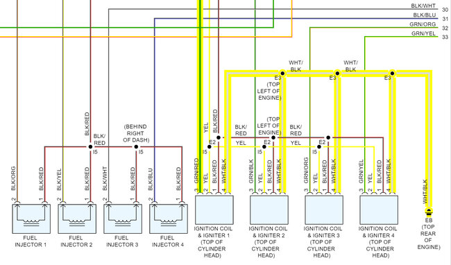
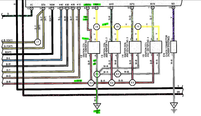
Hello, hopefully these wire colors are correct, I will check the OEM to verify, but black/red is a shared 12v feed, White/Black is a shared Ground, the Yellow wire is another shared wire to the ECM labelled IGF so that is a feedback circuit, and the green/red wire is the transistor control inside the number 1 ignition coil so that will most likely be a 4 volt square wave that signals the transistor on. These are smart coils, as they call them. To see the transistor on signal you'll need a scope to verify that it most likely will not light a test light. If it does it will be very dim. But I will verify the colors to make sure they are correct.
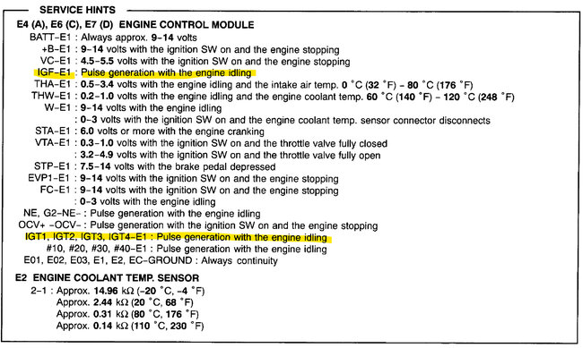
Ok the colors are correct on the aftermarket diagrams, service info doesn't say what voltage level the transistor on signal is, but it is usually a 0-to-4-volt square wave signal. The feedback circuit might be the same, since it's a shared circuit it will be a continuous signal back to the ECM to verify that they each fired.
It's unusual for a shorted coil to take out the ECM coil driver in these setups, for a 2 wire coil it happens all the time, but with these having the transistor built into the coil, which will fail and protect the ECM from any high current flow. Unlike a 2-wire coil where they short out and can take out the ECM driver pretty fast.
Images (Click to make bigger)
Wednesday, January 11th, 2023 AT 1:53 PM


