Hi aquiles,
Here are the testing procedures.
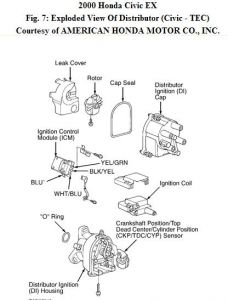
1. Turn ignition off. Remove distributor cap, rotor and leak cover (TEC). Disconnect wires from ICM. Turn ignition on. Check for voltage between ground and Black/Yellow wire. If battery voltage exists, go to next step. If battery voltage does not exist, check for open in Black/Yellow wire between ICM and IGN COIL fuse No. 9 (15-amp) located in underdash fuse/relay box.

2. Ensure ignition is on. Check for voltage between ground and Blue 2 wire (Hitachi) or White/Blue wire (TEC). If battery voltage exists, go to next step. If battery voltage does not exist, check ignition coil operation. If ignition coil is okay, check Blue 2 wire (Hitachi) or White/Blue wire (TEC) between ignition coil and ICM.
3. Turn ignition switch off. On all models except D16Y5 engine with M/T, disconnect PCM 25- pin connector "B". On D16Y5 engine with M/T, disconnect PCM 32-pin connector "A". On all models, check for continuity in Yellow/Green wire between ICM and PCM 25-pin connector "B" terminal No. 13 (except D16Y5 engine with M/T) or PCM 32-pin connector "A" terminal No. 20 (D16Y5 engine with M/T). If continuity exists, go to next step. If continuity does not exist, repair open in Yellow/Green wire.
4. Check for continuity between ground and Yellow/Green wire. If continuity does not exist, go to next step. If continuity exists, check for short to ground in Yellow/Green wire.
5. Check for continuity in Blue 1 wire between ICM and 2-pin, Natural tachometer test connector. Tachometer test connector is located at left rear corner of engine compartment, behind strut tower. If continuity exists, go to next step. If continuity does not exist, check for open in Blue 1 wire. 6. Check for continuity between ground and Blue 1 wire. If continuity exists, check for short to ground in Blue 1 wire. If continuity does not exist, wiring is okay at this time. Replace ICM.
Sunday, May 31st, 2009 AT 2:10 AM


