Hi mark4261956,
Thank you for the donation.
Yes, the code is for the TDC sensor which is inside the distributor. However before replacing the item, check if it is a fault with the wiring. The TDC sensor can be tested with a DVOM set to resistance function.
DTC P0335, P0336, P1361, P1362, P1381 & P1382: CKP/TDC/CYP SENSOR
NOTE:
CKP/TDC/CYP sensor is built into distributor and is serviced by replacing the distributor ignition housing.
NOTE:
If DTC P1359 is set when DTC P0335, P0336, P1361, P1362, P1381 and/or P1382 is set, trouble shoot DTC P1359 first.
1. Perform PCM reset procedure. Start engine. If DTC P0335, P0336, P1361, P1362, P1381 and/or P1382 are indicated, go to next step. If specified DTCs are not indicated, problem is intermittent. System is okay at this time. Check for poor connections or loose wires at CKP/TDC/CYP sensor distributor and PCM connectors. Repair as necessary.
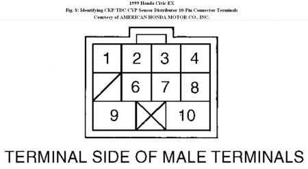
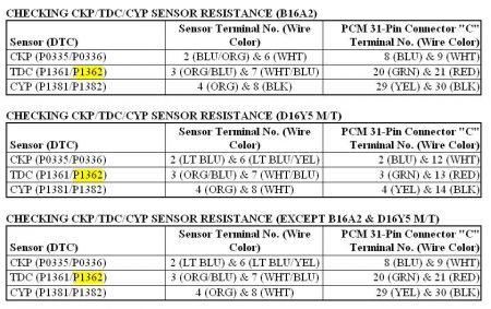
2. Turn ignition off. Disconnect CKP/TDC/CYP sensor distributor 10-pin connector. Measure resistance between CKP/TDC/CYP sensor terminals. See appropriate CHECKING CKP/TDC/CYP SENSOR RESISTANCE table. See Fig. 8 . If resistance between specified sensor terminals is 350-700 ohms, go to next step. If resistance is not 350-700 ohms, replace distributor ignition housing.
3. Check for continuity between ground and each specified CKP/TDC/CYP sensor terminal. See appropriate CHECKING CKP/TDC/CYP SENSOR RESISTANCE table. See Fig. 8 . If continuity does not exist, go to next step. If continuity exists, replace distributor ignition housing.
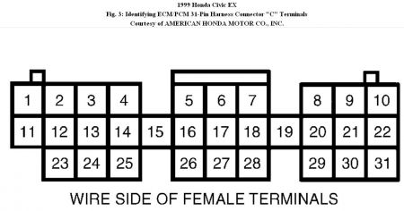
4. Reconnect CKP/TDC/CYP sensor distributor 10-pin connector. Disconnect PCM 31-pin connector "C". Measure resistance between specified PCM 31-pin harness connector "C" terminals. See CHECKING CKP/TDC/CYP SENSOR RESISTANCE table. See
Fig. 3 . If resistance between specified connector terminals is 350-700 ohms, go to next step. If resistance is not as specified, check for open in suspect wire between PCM and CKP/TDC/CYP sensor circuit.
5. On D16Y5 engine with M/T, check for continuity between ground and PCM 31-pin harness connector "C" terminals No. 2, 3 and 4 individually. See Fig. 3 . On all models except D16Y5 engine with M/T, check for continuity between ground and PCM 31-pin harness connector "C" terminals No. 8, 20 and 29 individually. See Fig. 3 . On all models, if continuity exists, check for short in suspect circuit. If continuity does not exist, substitute a known-good PCM and recheck. If symptom or indication goes away, replace original PCM.
Replacement of the distributor is not difficult as it is held onto the cylinder head by 3 bolts and 2 wiring connectors that has to be disconnected.
It would only fit in one way as the key slot is offset.
The only thing you need to do after installation is to get a timing light to check if the ignition timing is correct.
Friday, October 8th, 2010 AT 8:22 AM


