Hi weatherjack, Welcome to 2carpros and TY for the donation
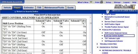
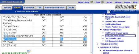
Scan the computer for codes-Could be just a shift control solenoid circuitry problem if its doing it again this time. Double check the wiring back to the computer and check for loose connector/s, shorts and opens-or trial by error with the PCM
Courtesy of AMERICAN HONDA MOTOR CO., INC.
COUNTERSHAFT SPEED SENSOR
Disconnect harness connector from countershaft speed sensor located on top of transaxle. See Fig. 5 . Using a DVOM, measure resistance between sensor terminals. Replace countershaft speed sensor if resistance is not 400-600 ohms.
LOCK-UP CONTROL SOLENOID VALVE/SHIFT CONTROL SOLENOID VALVE "A" ASSEMBLY
Lock-up control solenoid valve/shift control solenoid valve "A" assembly is located on transaxle. Disconnect harness connector at valve assembly. See Fig. 5 .
Using a DVOM, measure resistance between ground and terminal No. 1 (lock-up control solenoid valve), then between ground and terminal No. 3 (shift control solenoid valve "A"). See Fig. 14 .
Resistance should be 12-25 ohms. Replace lock-up control solenoid valve/shift control solenoid valve "A" assembly if resistance of either solenoid valve is not within specification.
Check lock-up control solenoid valve/shift control solenoid valve "A" operation. Ensure solenoid valve body is grounded. Apply battery voltage to terminal No. 1 (lock-up control solenoid valve), or terminal No. 3 (shift control solenoid valve "A").
A clicking sound should be heard, indicating solenoid valve operation. Replace lock-up control solenoid valve/shift control solenoid valve "A" assembly if either solenoid valve fails to operate.
Fig. 14: Lock-Up Control Solenoid Valve Harness Connector Terminals
Courtesy of AMERICAN HONDA MOTOR CO., INC.
MAINSHAFT SPEED SENSOR
Disconnect harness connector from mainshaft speed sensor located on side of transaxle. See Fig. 5 . Using a DVOM, measure resistance between sensor terminals. Replace mainshaft speed sensor if resistance is not 400-600 ohms.
SHIFT CONTROL SOLENOID VALVE "B"/"C"
Shift control solenoid valves are located on transaxle. See Fig. 5 . Disconnect harness connector at shift control solenoid valves.
Using a DVOM, measure resistance between ground and terminal No. 1 and No. 2 of each solenoid valve. See Fig. 15 .
Resistance should be 12-25 ohms. Replace shift control solenoid valve "B"/"C" if resistance of either solenoid valve is not within specification.
Check shift control solenoid valve operation. Apply battery voltage to terminal No. 2 of each solenoid valve. Connect terminal No. 1 of each solenoid to negative battery terminal.
A clicking sound should be heard, indicating solenoid valve operation. Replace shift control solenoid valve "B"/"C" assembly if either solenoid valve fails to operate.
Fig. 15: Shift Control Solenoid Valve Harness Connector Terminals
Courtesy of AMERICAN HONDA MOTOR CO., INC.
THROTTLE POSITION (TP) SENSOR
TP sensor should input a .5-volt signal to PCM at closed throttle. At full throttle, signal should be approximately 4.5 volts. Voltage should change smoothly as throttle valve is opened and closed. If voltage is not as specified, check throttle position sensor wiring circuit. See


Sunday, October 24th, 2010 AT 12:23 AM

