Ground issue at the blower motor?

2003 DODGE DURANGO
215,000 MILES • 4.7L • AUTOMATIC
Avatar
KMILL43
  • MEMBER
  • 5 POSTS
Hello, I've read previous questions about the blower motor with power issues. I've changed out the resistor block, a/c heater panel,and checked and replaced the blower motor. motor will come on if I ground it to the body. Power is coming to the motor from the harness, but won't work when you turn the selector switch on in the panel. All fuses are good and also the relay. Is there a way to bypass or tap into a ground source from the center panel? all lights and other settings work. Also I have a single (front) system, not front and rear system if that makes any difference. Thanks
Aug 26, 2026 at 9:30 AM
Advertisement
Avatar
CARADIODOC
  • Experienced Mechanic
  • 34,369 POSTS
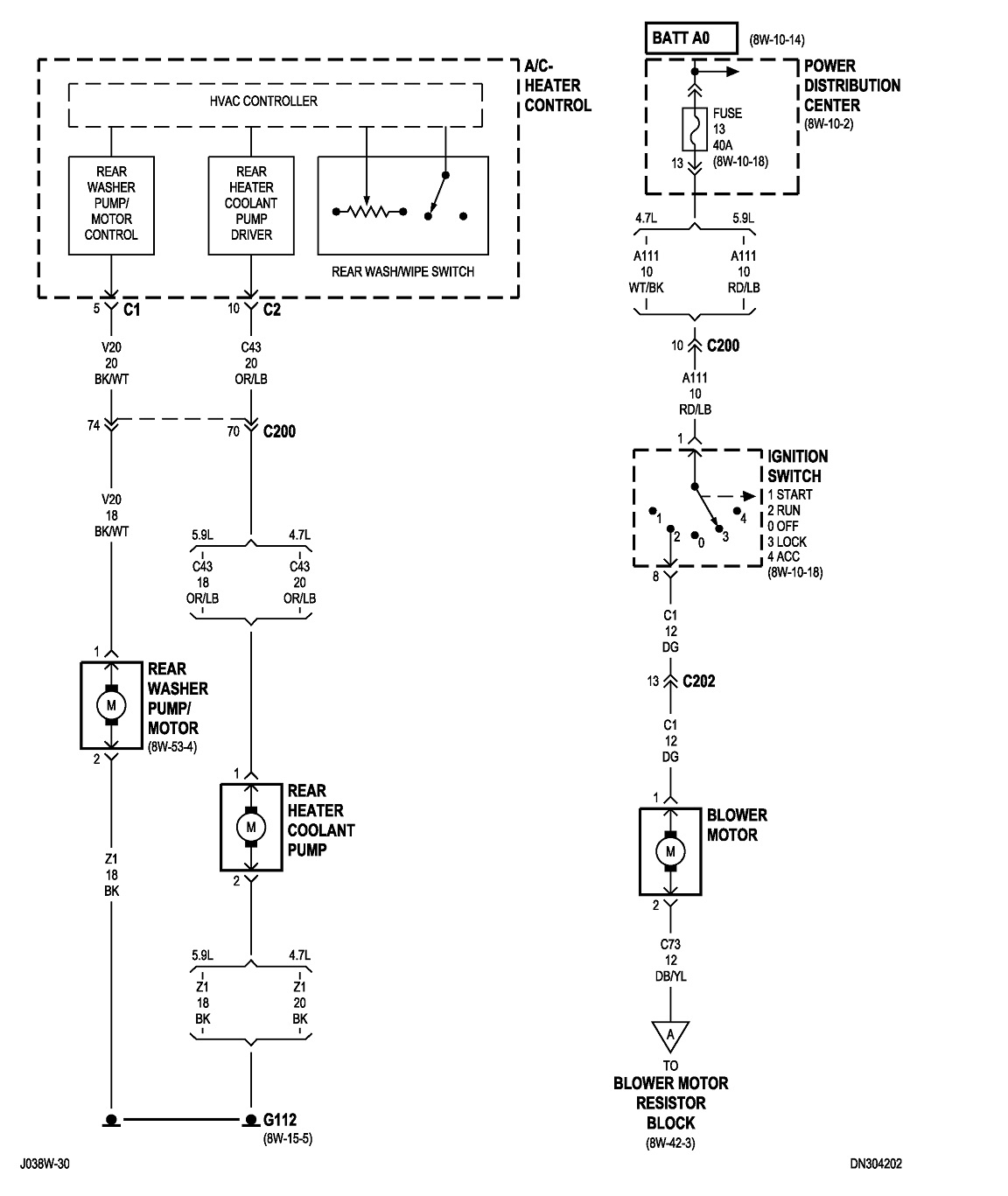
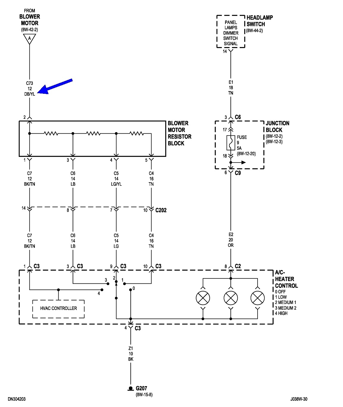
This circuit is upside down compared to what you're probably used to seeing. By grounding the motor wire, you're bypassing the resistor assembly and the speed switch. The circuit is grounded at the speed switch, not at the motor like they used to do.

These two diagrams show the fan circuit. You're grounding at point "A" at the lower right in the first diagram, and where I put the blue arrow at the top of the second diagram.

Use a test light to check for voltage on the black wire at the HVAC control panel, pin 4. If you find anything there, there's a break in that wire. If you find 0 volts, the better suspect is a burned connection on the dark blue / yellow wire at the resistor assembly. That would prevent fan operation on all speeds.

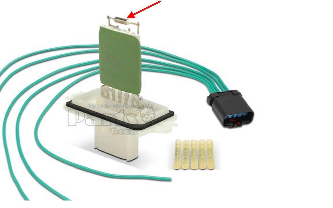
Also, while not shown in this diagram, resistor assemblies usually have a thermal fuse built in. It typically looks like a small silver cylinder. If you have one in your new assembly and it is burned open, it is due to tight bearings in the motor. Tight bearings cause the motor to slow down and draw higher than normal current. My red arrow is pointing to the resistor in the third photo.

Let me know what you find with these voltage tests, then we'll figure out where to go next.
Aug 26, 2026 at 2:33 PM
Avatar
KMILL43
  • MEMBER
  • 5 POSTS
Thank you for the reply, I'll double check everything again. also to check pin 4 do I need to find a power source to connect to? Thermal fuse is good ,no sign of being burnt or charred. also about you're right about me connecting the db/yl wire. the 1st time when I did it, I thought it might help ground the whole circuit but it only made the motor run at high speed so I removed it
Aug 26, 2026 at 5:33 PM
Avatar
KMILL43
  • MEMBER
  • 5 POSTS
Please disregard my question about the test light, this Houston heat fried my brain for a minute.LOL. Yes I am getting voltage from pin # 4
Aug 26, 2026 at 6:26 PM
Avatar
KMILL43
  • MEMBER
  • 5 POSTS
I am also getting continuity from pin4 to the resistor harness in the low-tan, #2-lt green,high-black/tan positions. off position is giving a "static sort of feedback. nothing from #3 at the panel or the blue/yellow or light blue at the resistor block.
Aug 26, 2026 at 6:49 PM
Avatar
CARADIODOC
  • Experienced Mechanic
  • 34,369 POSTS
To check for voltage on pin 4, the test light's clip lead must be on a good, paint and rust-free body panel or bolt.

By grounding the dark blue / yellow wire, you proved everything up to that point is okay.

You won't see a thermal fuse that has burned open. The fuse element is inside the protective metal cylinder. They can only be tested with an ohm meter by doing a continuity test, or we can rule them out with voltage tests.

Go to the resistor connector and back-probe the dark blue / yellow terminal alongside the wire. Also unplug the connector and see if that terminal is black or if the plastic connector body is melted. If you find 12 volts on that wire, set the speed switch to the slowest speed, then check for voltage on any of the other four wires and tell me what you find.

To be more accurate, unplug the speed switch or entire heater control panel, then check for voltages again on all five resistor wires and tell me what you find. I'll be back tomorrow to see how you did.
Aug 27, 2026 at 5:51 PM
Avatar
KMILL43
  • MEMBER
  • 5 POSTS
Thank you for your time and trouble with my issue, sorry it took me longer than expected to respond. I took everything apart, tested all wiring and circuits etc, put everything back together, now it's working normally again. The only minor issue which is not a big deal at all, is that medium 2 doesn't blow all other speeds work great. Other than that wifey is happy again. yay. Again THANK YOU!!!
Aug 30, 2026 at 7:10 AM
Avatar
CARADIODOC
  • Experienced Mechanic
  • 34,369 POSTS
Dandy. You have burned or corroded terminals on the resistor assembly's connector. Unplugging it and reconnecting it scratches temporary clean spots that make better contact, . . . for a while. That is not the permanent fix.

The proper repair for burned terminals is always to replace both the part and the connector or terminals at the same time. Leaving one in there with degraded terminals will result in a less than perfect connection. That means electrical resistance which means heat buildup and a future repeat failure, typically within weeks.

If the resistor assembly is new, that doesn't have to be replaced again unless you keep using it this way. You do have to replace the terminals in the connector. You might find a good, used connector in a salvage yard. The better, but more expensive approach is to order a new connector from an auto parts store. They have multiple, large books that list just about every electrical connector you can imagine. They come with about six to eight inches of wire that you splice to your truck's wire harness. Wire colors are usually different, so you have to go by their locations in the connector and match those up.

Another approach is to go to the Chrysler dealer's parts department. They have terminal kits that cover all of their models. You can replace all of the terminals, one at a time, by crimping them to the wires, but I always solder them too to insure a solid connection. The problem is when terminals are overheated, about four inches of each wire will be hardened from the heat and solder won't adhere to it. That four inches must also be replaced by splicing those sections in, then installing the terminals.

The last thing to be aware of is often competent do-it-yourselfers will poke a test light into the terminal to take a reading. If it gets pushed in far enough, it will spread the female terminal, resulting in a bad or intermittent connection. It could still work for a while, but again, with a poor connection and heat build-up. If you catch a spread terminal right away, you can use a pick to go in alongside the terminal and press it back into shape to make a tighter fit.
Aug 30, 2026 at 4:34 PM
Join 2CarPros for free, one of the most advanced car repair communities on the internet. From first-time drivers to seasoned mechanics, everyone is welcome to reply, share details, and get better answers. You can add a temporary image or video first; uploads are limited to 20 MB.
Ask a Free Question
Repair Safety Notice: This information is for general instructional purposes only. Vehicle repair can be dangerous. Verify all information, follow manufacturer service procedures, use proper tools and safety equipment, and consult a qualified repair shop when needed.