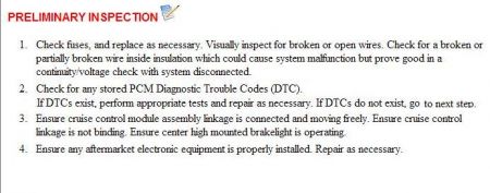
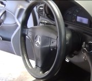
Without a scan tool, about all you can do is check the switch. Does the cruise power on, as indicated by the icon, it just don't set or resume? The switch receives power from the BCM(body control), and the signal is interpreted in the BCM as well. If the power switch functions, it is receiving power and ground from the BCM on the same circuit that all the switch functions use. If you disconnected the cruise switch, pins 1 and 3 are the circuits to test. Here are the resistance values:
Important: The cruise control ON/OFF switch must be ON in order to properly measure the resistance of the - SET, the + RES, and the Cancel switches.
With the ignition OFF, remove the inflatable restraint steering wheel module. If you need to remove the steering wheel inflator for access, here is the procedure.
On the back side of the steering wheel, there are 2 access holes. Using a 3-4 mm T handle allen wrench, insert in a cross car (Horizontally) direction and slightly outboard (handle towards I/P) push in 40mm (1 1/2in) to engage release spring.
With the ignition OFF, measure the resistance between terminals 1 and 3 at the cruise control switch side of the connector. Individually activate and hold each cruise control function switch and compare the resistance reading to the values on the schematic for the ON/OFF, - SET, the + RES, and the Cancel switches.
� � ’ If any of the resistance measurements for the OFF, ON, - SET, + RES, and Cancel switches are not within the listed resistance values, replace the cruise control switch assembly.
Function Switch
Minimum Resistance Value
Maximum Resistance Value
OFF
O.L.
O.L.
ON
6.5k Ohms
7.0k Ohms
- SET
2.2k Ohms
2.4k Ohms
+ RES
3.7k Ohms
3.8k Ohms
Cancel
1.4k Ohms
1.6k Ohms
And while you are in the area, you can also make some quick circuit verification.
Ignition OFF, Disconnect the harness connector of the cruise control switch.
Ignition ON, measure for 10 volts or greater at the cruise control supply voltage circuit pin 1/pink wire.
� � ’ If less than 10 volts, check for an open/high resistance or for a short to ground on the cruise control supply voltage circuit.
Ignition OFF, test for an open, for a high resistance, for a short to ground, or for a short to voltage in the cruise control switch signal circuit pin 3/gray wire, and also for reference, pin 3 of connector C1(light green 27 pin) at the BCM.
The circuits and the component tests are normal, replace the BCM, I would not replace the BCM without checking further with a scan tool.
As far as symptoms are concerned, are the brake lights functioning correctly, is there any check engine light observed, and are any of the cruise switches possibly sticking, or stuck? There are concerns that can inhibit operation, and it may lead to having that scan tool as mentioned previously.
And while you are in the area, you can also make some quick circuit verification.
Ignition OFF, Disconnect the harness connector of the cruise control switch.
Ignition ON, measure for 10 volts or greater at the cruise control supply voltage circuit pin 1/pink wire.
� � ’ If less than 10 volts, check for an open/high resistance or for a short to ground on the cruise control supply voltage circuit.
Ignition OFF, test for an open, for a high resistance, for a short to ground, or for a short to voltage in the cruise control switch signal circuit pin 3/gray wire, and also for reference, pin 3 of connector C1(light green 27 pin) at the BCM.
The circuits and the component tests are normal, replace the BCM, I would not replace the BCM without checking further with a scan tool.
Friday, March 5th, 2010 AT 10:30 PM


