Hey Jackie/Jess and MR Jackie..LOL.
Did you see my last 2 post's ?? anyway as you said it is late .. will try again in the morning !!
I need you to clean the MAF sensor it sems to be running rich (overfueling) .. also I am including these test's if you could try them in the morning ? these tests are designed for a GMC code reader do not worry if your reader will not perform these test .. just do the voltage test's ..
DTC P0405: EGR POSITION SENSOR SIGNAL VOLTAGE EXCESSIVELY LOW
NOTE:For circuit reference, see WIRING DIAGRAMS article.
Circuit Description
The PCM monitors EGR valve pintle position input to ensure that valve responds properly to commands from PCM and to detect a fault if the pintle position sensor circuit is open or shorted. If PCM detect an excessively low EGR position sensor signal voltage, this DTC will set.
Code Enable Criteria
Conditions for running DTC:
Ignition voltage is greater than 11.7 volts.
Engine is running.
Conditions for setting DTC:
EGR position sensor voltage is less than 0.14 volt.
Conditions present for 5 seconds.
Diagnostic Procedures
Perform powertrain diagnostic system check. See POWERTRAIN DIAGNOSTIC SYSTEM CHECK under SELF-DIAGNOSTIC SYSTEM. After performing powertrain diagnostic system check, go to next step.
NOTE:If DTC P1635 is set, diagnose DTC P1635 first. Go to DTC P1635.
Turn ignition on, with engine off. Using scan tool, observe EGR position sensor voltage parameter. If scan tool indicates that EGR position sensor voltage is less than 0.14 volt, go to step 4. If scan tool does not indicate that EGR position sensor voltage is less than 0.14 volts, go to next step.
Observe the FREEZE FRAME/FAILURE RECORDS data for this DTC. Turn ignition off for 30 seconds. Operate vehicle within the conditions for running the DTC or as close to FREEZE FRAME/FAILURE RECORDS data observed. See CODE ENABLE CRITERIA. If DTC resets, go to next step. If DTC does not reset, problem is intermittent.
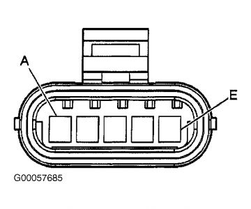
Turn ignition off. Disconnect EGR valve harness connector. Connect a fused jumper wire between EGR valve harness connector terminals "C" (Brown wire) and "D" (Gray wire). See Fig. 5. Turn ignition on, with engine off. Using scan tool, observe EGR position sensor parameter. If scan tool indicates that EGR position sensor is about 100 percent, go to step 10. If scan tool does not indicate that EGR position sensor is about 100 percent, go to next step.
Disconnect fused jumper wire. Using a DVOM, check voltage between EGR valve harness connector terminals "B" (Black wire) and "D" (Gray wire). If voltage reading is about 5 volts, go to step 9. If voltage reading is not about 5 volts, go to next step.
Turn ignition off. Check for open or high resistance in Gray wire between EGR valve and PCM. Repair as necessary. After repairs, go to step 15. If circuit is okay, go to next step.
Check for short to ground in 5-volt reference circuits from other components. See WIRING DIAGRAMS article. Repair as necessary. After repairs, go to step 15. If circuits are okay, go to next step.
Connect DVOM between EGR valve harness connector terminals "B" (Black wire) and "D" (Gray wire). Observe voltage while disconnecting all sensors, one at a time, that use a 5-volt reference signal. A change in voltage indicates the faulty component. Replace that component as necessary. After repairs, go to step 15. If no problem is found, go to step 11.
Turn ignition off. Check for short to ground, high resistance or open in Brown wire between EGR valve and PCM. Repair as necessary. After repairs, go to step 15. If circuit is okay, go to step 11.
Turn ignition off. Check for short between Brown and Red wire at EGR valve harness connector. Repair as necessary. After repairs, go to step 15. If circuits are okay, go to step 12.
Check for poor connections at PCM harness connector. Repair as necessary. After repairs, go to step 15. If connections are okay, go to step 14.
Check for poor connections at EGR valve harness connector. Repair as necessary. After repairs, go to step 15. If connections are okay, go to next step.
Replace EGR valve. After replacing EGR valve, go to step 15.
Replace PCM. Perform PCM relearn procedure. See POWERTRAIN CONTROL MODULE under PROGRAMMING. After replacing EGR, go to next step.
Turn ignition on, with engine off. Using scan tool, clear DTCs. Turn ignition off for 30 seconds. Operate vehicle within the conditions for running the DTC. See CODE ENABLE CRITERIA. If DTC runs and passes, go to next step. If DTC resets, go to step 2.
Using scan tool, observe the stored information and Capture info. If scan tool displays any undiagnosed DTCs, diagnose affected DTCs. See DIAGNOSTIC TROUBLE CODE DEFINITIONS. If no DTCs are displayed, system is okay.
figure 5)

let me know

Sunday, March 15th, 2009 AT 9:33 PM


