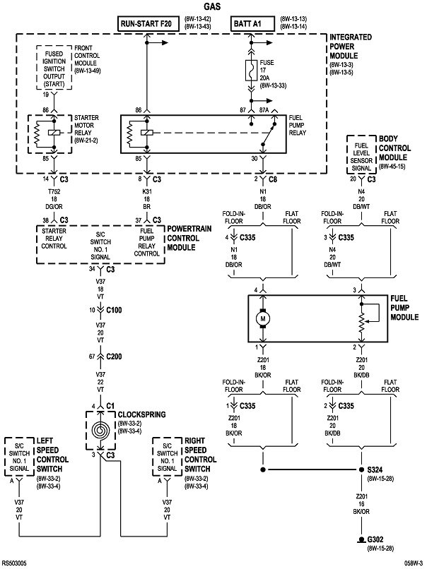
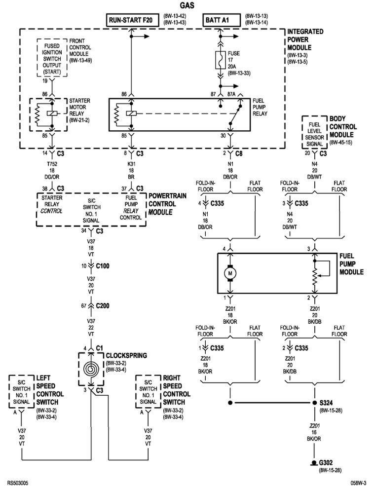
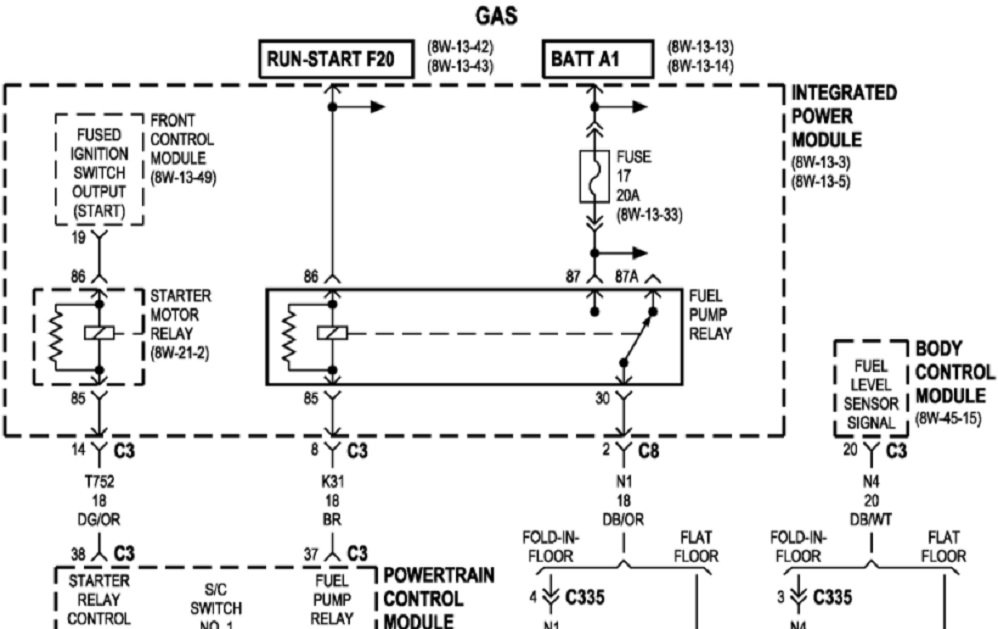
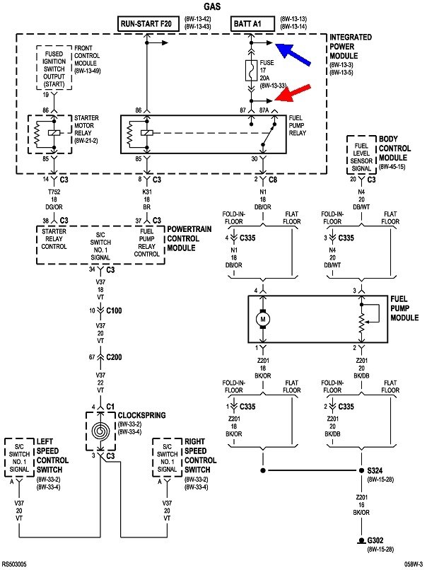
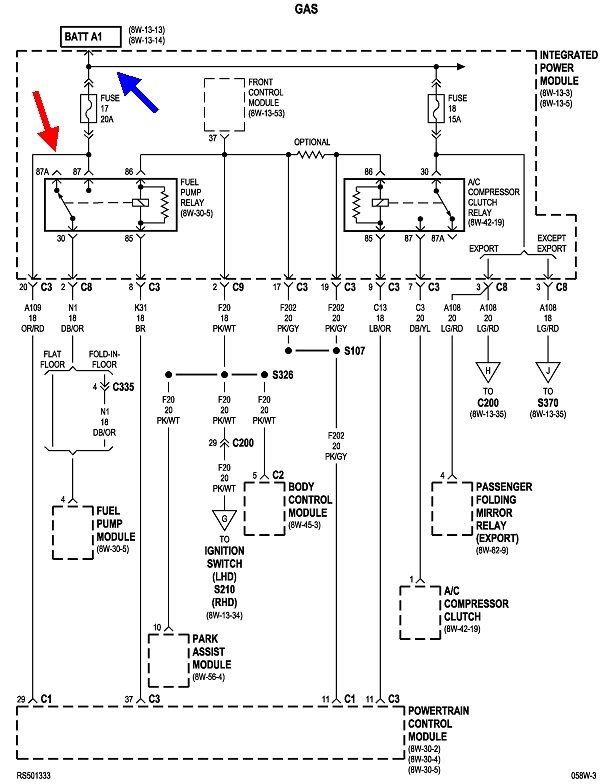
Good catch. I overlooked those arrows. The second diagram is part of the "Power and Grounds" section. It shows where the two arrows related to fuse 17 go to.
The blue arrow goes to fuse 18. That's not protected by fuse 17. The red arrow goes to the Engine Computer and is protected by fuse 17. It's very unlikely the computer is shorted intermittently on that circuit. The better suspect would be the orange/red wire itself is grounded to the body sheet metal. This used to be a source of problems on '95 and older models where the harness that runs along the left inner fender and under the battery tray would slide back and forth as the engine rocks. The insulation on some of the wires would rub off as well as the paint, then intermittent shorts would occur. One big clue is the fuses usually blew the instant the driver started to accelerate in "drive" or "reverse".
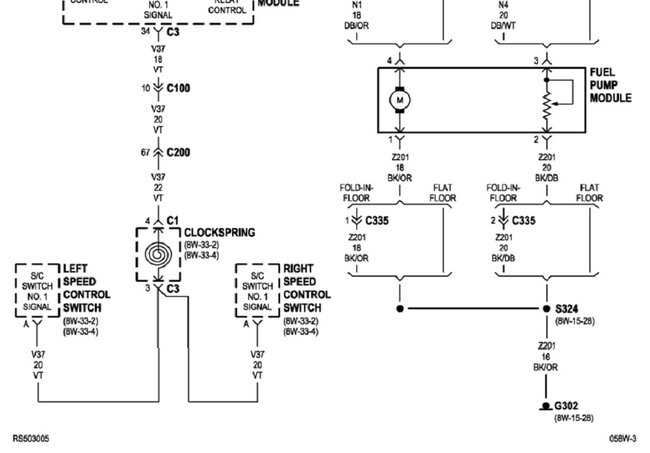
The way I would approach this is to replace the fuel pump relay with a 15-amp fuse, and drive the van like that until the problem occurs. If the orange / red wire is intermittently shorted to ground, fuse 17 will still blow when the short occurs. If the dark blue / orange wire to the fuel pump is grounding out, the temporary fuse will blow as long as it is smaller than the 20-amp fuse 17.
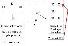
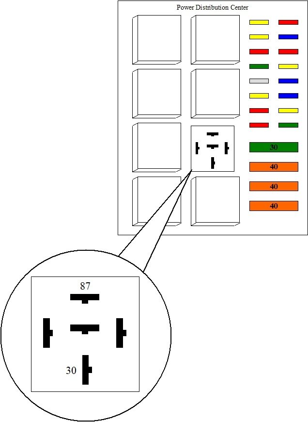
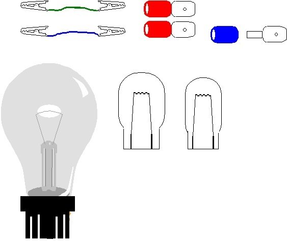
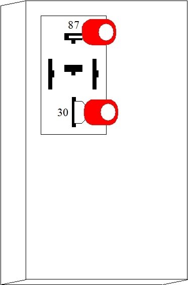
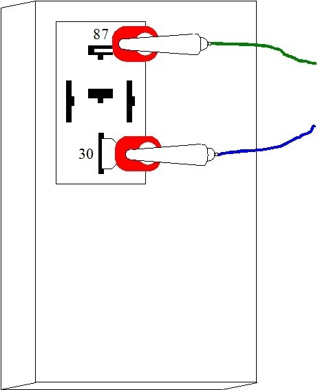
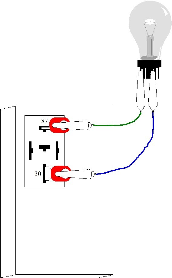
To bypass the fuel pump relay, remove it from the socket, then plug in a pair of universal crimp-style spade terminals into terminals 30 and 87. Use a pair of small jumper wires to connect them to the temporary fuse. For the benefit of others researching this topic, here's drawings I put together previously to show how this is done. The bulb is used to protect the circuit when a short occurs. Use a fuse instead of that bulb. The common 3057 brake light bulb shown will only allow a maximum of one amp to pass. That's not enough to run the fuel pump.
Be aware using a fuse this way presents a very real safety concern and should be discontinued as soon as you get useable results. Under normal operation, the Engine Computer turns the automatic shutdown, (ASD) relay and the fuel pump relay on for one second when the ignition switch is turned to "run", then they are turned back off until there's engine rotation, meaning cranking or running. That's done to insure fuel pressure is up for starting in case it bled down over days or weeks.
Once running, in the event a fuel line is ruptured in a crash, fuel pressure drops to 0 psi. With no pressure, the injectors won't inject fuel and the engine stalls. Once stalled, there's no signal pulses from the crankshaft position sensor or the camshaft position sensor. Loss of those signals tells the computer to turn the two relays off. That stops the fuel pump so it doesn't dump raw fuel on the ground where it would be a serious safety hazard. By using the fuse in place of the relay, the Engine Computer looses control and can't turn the fuel pump off. In fact, the pump will run non-stop constantly until the fuse is disconnected. If the fuse isn't disconnected when the engine is turned off, the fuel pump will run the battery dead within less than two hours.
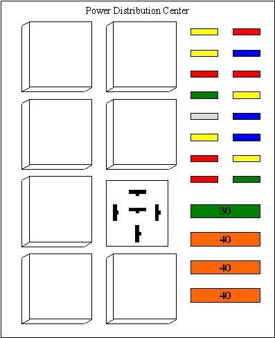
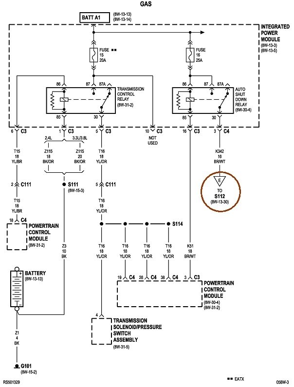
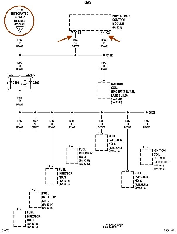
For my final comment of value, I added the last two diagrams to show the ASD relay circuits. Since the mid '80s, that relay feeds the injectors and ignition coil(s), as shown here, as well as the alternator's field circuit, oxygen sensor heaters, and in some cases, the fuel pump itself, or the fuel pump relay. One circuit that is usually overlooked is the additional circuit going back to the Engine Computer, shown with the two brown arrows. The computer thinks it turned the ASD relay on, and it gets verification of that on those two brown / white wires. (Those are also the 12-volt supplies for other circuits controlled by the computer).
The point of this sad story is the computer also expects to see 0 volts on those two wires when it turns the ASD relay off. My light bulb, (fuse) trick, for finding shorts will maintain 12 volts on those wires when it shouldn't be there, and that can set a diagnostic fault code on some models. That shouldn't prevent the engine from running, but to avoid future confusion, those fault codes should be erased once the diagnostic tests have been completed. I don't see such a "verification" circuit for the fuel pump relay, but it has likely been added on newer models.
If someone runs into this problem on a newer model with its much more sophisticated computers, and doing this makes the computer refuse to crank or run the engine, you'd have to cut the orange/ red wire and insert a smaller fuse in it, (which I highly discourage), or fashion four jumper wires for the relay, then cut one of them for terminal 30 or 87 and stick the fuse in there. That way you have the two circuits fused separately to help identify which one has the intermittent short, and you still have the relay with its switching action that will keep the computer happy.
Also, the computer often monitors the K31 18 brown circuit that it switches to ground to turn the fuel pump relay on. With the relay unplugged, it may detect the missing 12 volts it would normally see there and set a different fault code. If that creates a problem, you'll again have to use the relay and four jumper wires.
Images (Click to make bigger)
Friday, December 25th, 2020 AT 7:13 PM
