Hi,
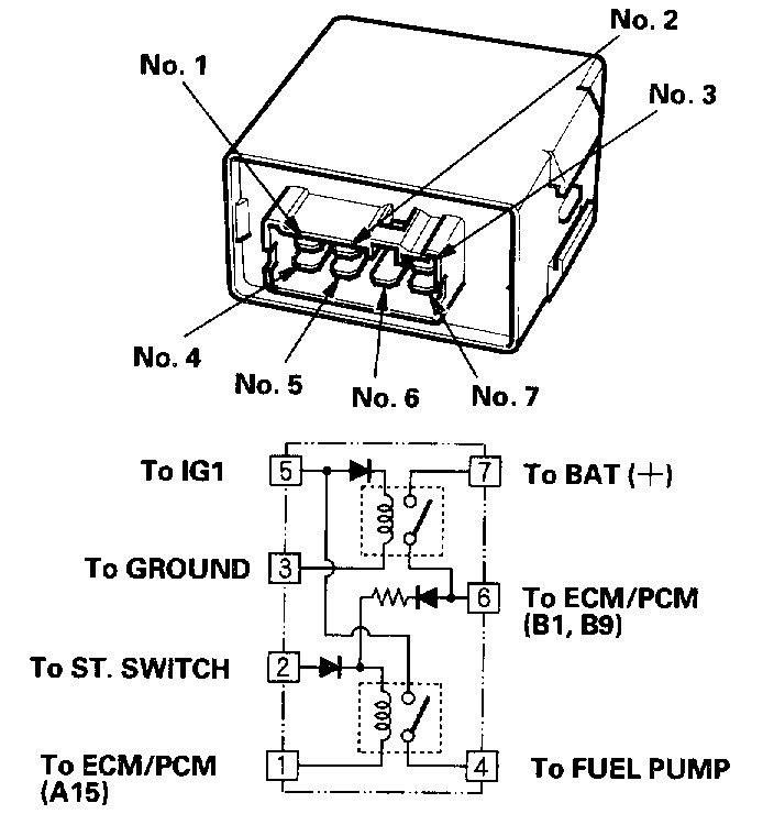
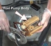
The PGM-FI relay contains two separate relays. One is energized whenever the ignition is on which supplies battery voltage to the ECM/PCM, power to the fuel injectors, and power for the second relay. The second relay is energized to supply power to the fuel pump for two seconds when the ignition is switched on, and when the engine is running.
Did you get a direct replacement for the relay when you replaced it? If you did, we need to see why the second relay keeps receiving a signal to constantly feed power to the pump. Since you noticed the fan running constantly, there is likely a short to power at some point or the PCM may have failed.
__________________________
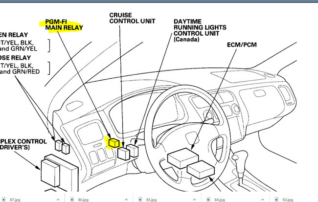
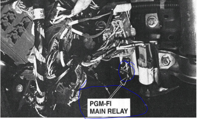
Here are directions to diagnose a relay problem. The attached pics correlate with the directions.
_________________________
1999 Honda Accord EX Coupe V6-3.0L
Component Tests and General Diagnostics
Vehicle Powertrain Management Fuel Delivery and Air Induction Fuel Pump Fuel Pump Relay Testing and Inspection Component Tests and General Diagnostics
COMPONENT TESTS AND GENERAL DIAGNOSTICS
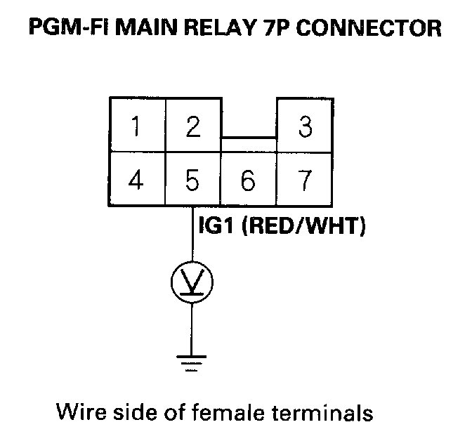
1. Turn the ignition switch OFF, then disconnect the PGM-FI main relay 7P connector.
Pic 1
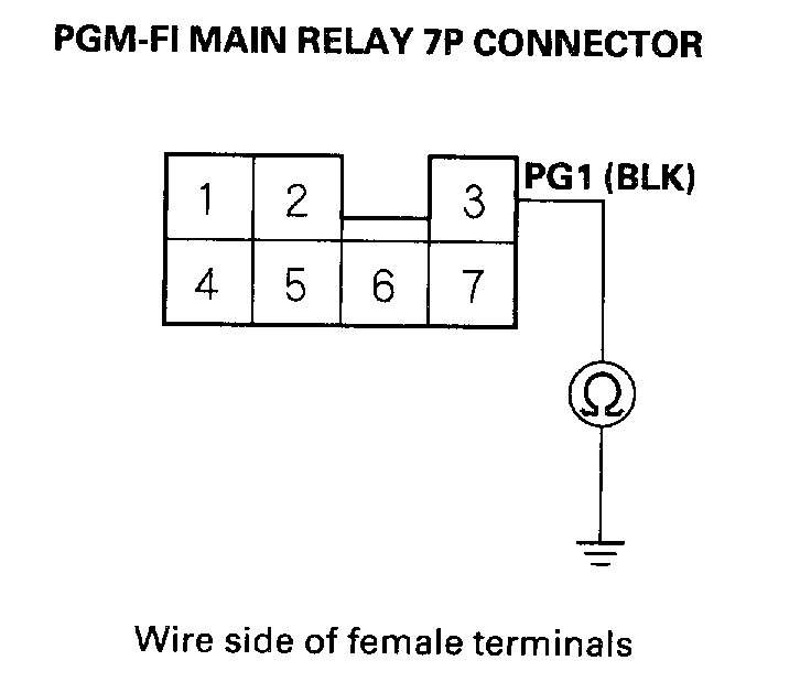
2. Check for continuity between body ground and the PGM-FI main relay 7P connector terminal No.3.
Is there continuity?
YES-Go to step 3.
NO-Repair open in the wire between the PGM-FI main relay and G101.
Pic 2
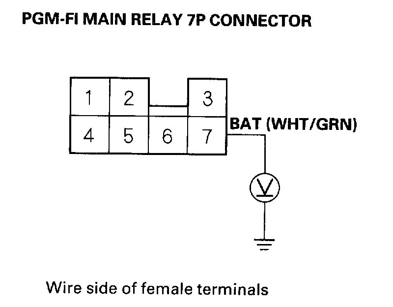
3. Measure voltage between body ground and the PGM-FI main relay 7P connector terminal No.7.
Is there battery voltage?
YES-Go to step 5.
NO-Go to step 4.
4. Check for a blown ACG S (15 A) fuse in the under- hood fuse/relay box.
Is the fuse blown?
YES-Repair the short in the wire between the PGM-FI main relay and the ACG S (15 A) fuse.
NO-Repair the open in the wire between the PGM-FI main relay and the ACG S (15 A) fuse.
Pic 3
5. Turn the ignition switch ON (II), and measure voltage between body ground and the PGM-FI main relay 7P connector terminal No.5.
Is there battery voltage?
YES-Go to step 7.
NO-Go to step 6.
6. Check for a blown No.1 FUEL PUMP (15 A) fuse in the driver's under-dash fuse/relay box.
Is the fuse blown?
YES-Repair the short in the wire between the PGM-FI main relay and the No.1 FUEL PUMP (15 A) fuse.
NO-Repair the open in the wire between the PGM-FI main relay and the No.1 FUEL PUMP (15 A) fuse.
Pic 4
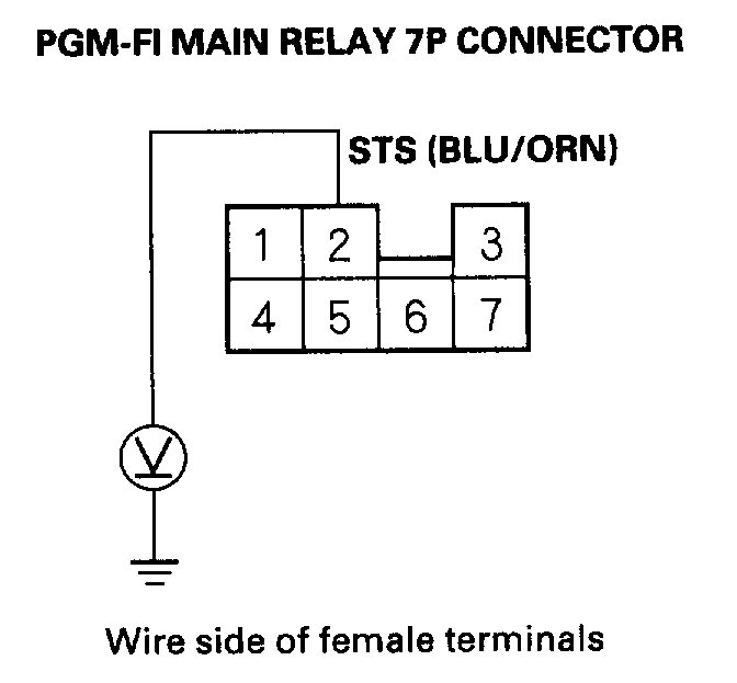
7. Push the clutch pedal in, or shift to Park, then turn the ignition switch to the START (III) position, and measure voltage between body ground and the PGM-FI main relay 7P connector terminal No.2.
Is there battery voltage?
YES-Go to step 9.
NO-Go to step 8.
8. Check for a blown No.13 STARTER SIGNAL (7.5 A) fuse in the driver's under-dash fuse/relay box.
Is the fuse blown?
YES-Repair the short in the wire between the PGM-FI main relay and the No.13 STARTER SIGNAL (7.5 A) fuse.
NO-Repair the open in the wire between the PGM-FI main relay and the No.13 STARTER SIGNAL (7.5 A).
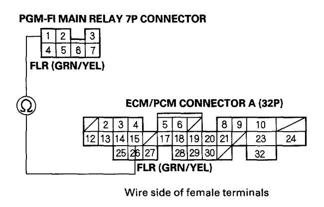
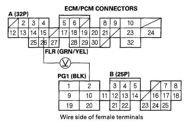
9. Turn the ignition switch OFF, and disconnect the ECM/PCM connector A (32P).
Pic 5
10. Check for continuity between the PGM-FI main relay 7P connector terminal No.1 and the ECM/PCM connector terminal A15.
Is there continuity?
YES-Go to step 11.
NO-Repair open in the wire between the PGM-FI main relay and the ECM/PCM (A15).
11. Reconnect the ECM/PCM connector A (32P) and the PGM-FI main relay 7P connector.
Pic 6
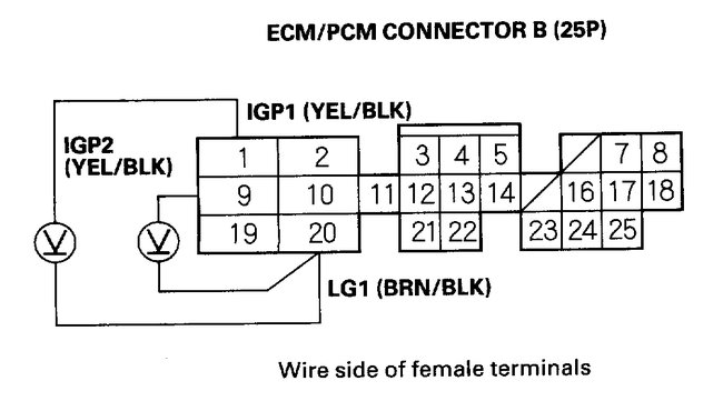
12. Turn the ignition switch ON (II), and measure voltage between the ECM/PCM connector terminals B1 and B20, and between B9 and B20.
Is there battery voltage?
YES-Go to step 13.
NO-Check for an open in the wires between the PGM-FI main relay and the ECM/PCM (B1, B9). If the wires are OK, replace the PGM-FI main relay.
Pic 7
13. Turn the ignition switch OFF, then ON (II) again, and measure voltage between the ECM/PCM connector terminals A15 and B2 within the first two seconds after the ignition switch is turned ON (II).
Is there 1.0 V or less?
YES- PGM-FI main relay may be faulty: go to step 14.
NO-Substitute a known-good ECM/PCM and recheck. If prescribed voltage is now available, replace the original ECM/PCM.
See: Computers and Control Systems > Initial Inspection and Diagnostic Overview > Diagnostic Strategies
14. Remove the PGM-FI main relay.
Pic 8
15. Connect battery power to the PGM-FI main relay 7P connector terminal No.2 and connect ground to the PGM-FI main relay 7P connector terminal No.1. Then check for continuity between the PGM-FI main relay 7P connector terminals No.5 and No.4.
NOTE: Use the terminal numbers shown. Ignore the terminal numbers molded into the relay.
Is there continuity?
YES-Go to step 16.
NO-Replace the PGM-FI main relay and reset
16. Connect battery power to the PGM-FI main relay 7P connector terminal No.5, and connect ground to the PGM-FI main relay 7P connector terminal No.3. Then check for continuity between the PGM-FI main relay 7P connector terminals No.7 and No.6.
Is there continuity?
YES-Go to step 17.
NO-Replace the PGM-FI main relay and reset.
17. Connect battery power to the PGM-FI main relay 7P connector terminal No.6, and connect ground to the PGM-FI main relay 7P connector terminal No.1. Then check for continuity between the PGM-FI main relay 7P connector terminals No.5 and No.4.
Is there continuity?
YES-The PGM-FI main relay is OK.
NO-Replace the PGM-FI main relay and retest.
_________________________
Let me know if this helps or if you have other questions.
Take care,
Joe
Images (Click to make bigger)
Sunday, November 1st, 2020 AT 6:42 PM
