Hi,
As far as the TPS, it shouldn't get hot. Here is how to check it:
The Throttle Position Sensor (TPS) can be tested with a digital voltmeter.
- The center terminal of the sensor is the output terminal.
With the ignition switch in the ON position, monitor the output voltage at the center terminal wire of the connector -- while slowly moving the throttle from the idle position to Wide Open Throttle (WOT).
- At idle, TPS output voltage should be approximately 0.5 volts.
- At wide open throttle, TPS output voltage should be approximately 3.7 volts.
- The output voltage should gradually increase as the throttle plate moves slowly from idle to WOT.
_____________________
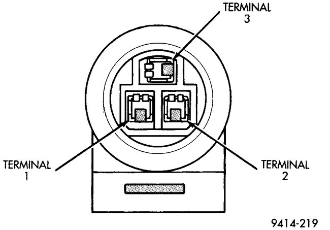
As far as the MAP, here are the directions. The attached pic correlates with the directions.
_____________________
1995 Dodge Neon L4-2.0L SOHC
Component Testing
Vehicle Powertrain Management Sensors and Switches - Powertrain Management Sensors and Switches - Computers and Control Systems Manifold Pressure/Vacuum Sensor Testing and Inspection Component Tests and General Diagnostics Component Testing
COMPONENT TESTING
Fig. 30 MAP Sensor Connector
Pic 1
NOTE: Complete testing of this component and its circuit is done at the system level. See: A L L Diagnostic Trouble Codes ( DTC ) > Manufacturer Code Charts > DTC Test - CODE TO TC TEST CHART (Checking for Trouble Codes)
CAUTION: When testing the MAP sensor, be sure that the harness wires are not damaged by the test meter probes.
1. Test the MAP sensor output voltage at the MAP sensor connector between terminals 1 and 3 (Fig. 30).
- With the ignition switch ON and the engine not running, output voltage should be 4 to 5 volts.
- The voltage should drop to 1.5 to 2.1 volts with a hot, neutral idle speed condition.
- If OK, go to next step.
- If not OK, go to step 3.
2. Test PCM terminal 29 for the same voltage described in the previous step to verify wire harness condition.
- Repair as required.
3. Test the MAP sensor ground circuit at sensor connector terminal 1 and PCM terminal 51.
- If OK, go to next step.
- If not OK, repair as required.
4. Test MAP sensor supply voltage between sensor connector terminals 2 and 1 with the key ON. The voltage should be approximately 5 volts (+/- 0.5V). Five volts (+/-0.5V) should also be at terminal 43 of the PCM.
- If OK, replace MAP sensor.
- If not OK, repair or replace the wire harness as required.
NOTE: Complete testing for this system or component can be found at the system level. See: A L L Diagnostic Trouble Codes ( DTC ) > Manufacturer Code Charts > DTC Test - CODE TO TC TEST CHART (Checking for Trouble Codes)
Image (Click to make bigger)
Monday, December 28th, 2020 AT 10:15 PM
