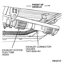
Exhaust system must be removed
Section 07-01: Transaxle, Automatic"”AX4S 1996 Windstar Workshop Manual
IN-VEHICLE SERVICE Procedure revision date: 06/15/2000
Vehicle Speed Sensor (VSS)
Removal
Disconnect battery ground cable (14301).
Separate upper and lower speedometer cable (17260) (if equipped) on left side of engine compartment below brake master cylinder (2140) and unclip speedometer cable from shift cable bracket.
Raise and suitably support vehicle on hoist.
Disconnect two heated oxygen sensor (HO2S) and two catalyst monitor sensor electrical connectors.
CAUTION: Failure to use the Exhaust Connector Holder T94T-6000-AH may result in leakage and reduced life of flex pipe.
Install Exhaust Connector Holder T94T-6000-AH to prevent undue stress on flexible portion of flex pipe. Offset the tool strap bolts so that the two flex pipe-to-Y pipe bolts are accessible and tighten tool bolts to 10 Nm (89 lb-in).

Remove two flex pipe-to-Y pipe bolts.
Remove Y pipe-to-transaxle case bracket bolt and nut.
Remove four Y pipe-to-exhaust manifold nuts and remove Y pipe assembly from vehicle.
WARNING: HEAT SHIELD HAS SHARP EDGES. THE USE OF GLOVES IS RECOMMENDED DURING HEAT SHIELD REMOVAL AND INSTALLATION TO PREVENT PERSONAL INJURY.
Carefully remove three push nuts and transaxle heat shield from transaxle.
Disconnect vehicle speed sensor (VSS) (9E731) electrical connector.
Remove VSS retaining bolt.
Remove VSS from speedometer cover (7A301).
Disconnect speedometer cable (if equipped) and remove VSS from transaxle.

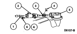
Item Part Number Description
1 9F714 Speedometer Cable (If Equipped)
2 9E731 Vehicle Speed Sensor
3 17292 Speedometer Driven Gear
4 "” Clip
5 7A031 Speedometer Cover
6 N602529 Bolt
A "” Tighten to 10 Nm (89 Lb-In)
Installation
Connect speedometer cable (if equipped) to VSS.
Install VSS into speedometer cover and secure with VSS retaining bolt. Tighten bolt to 10 Nm (89 lb-in).
Connect VSS electrical connector.
WARNING: HEAT SHIELD HAS SHARP EDGES. THE USE OF GLOVES IS RECOMMENDED DURING HEAT SHIELD REMOVAL AND INSTALLATION TO PREVENT PERSONAL INJURY.
Install transaxle heat shield and secure with three push nuts.
Install Y pipe assembly to vehicle and secure with four Y pipe-to-exhaust manifold nuts. Tighten nuts to 34-46 Nm (25-33 lb-ft).
Install Y pipe-to-transaxle case bracket bolt and nut. Tighten bolt and nut to 34-46 Nm (25-33 lb-ft).
Install two flex pipe-to-Y pipe bolts. Tighten bolts to 34-46 Nm (25-33 lb-ft).
Remove Exhaust Connector Holder T94T-6000-AH from flex pipe.
Connect two heated oxygen sensor (HO2S) and two catalyst monitor sensor electrical connectors.
Lower vehicle.
Connect upper and lower speedometer cable (if equipped) on left side of engine compartment below brake master cylinder and attach speedometer cable to shift cable bracket.
Connect battery ground cable.
SPONSORED LINKS
Wednesday, October 6th, 2010 AT 7:57 PM

