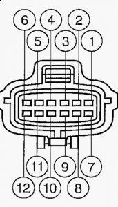
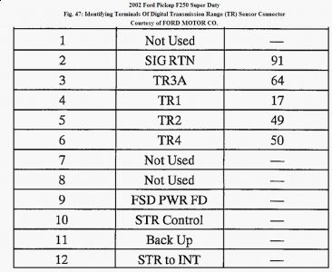
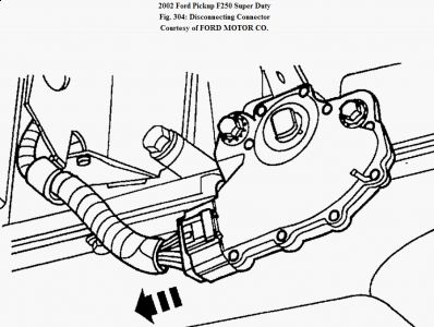
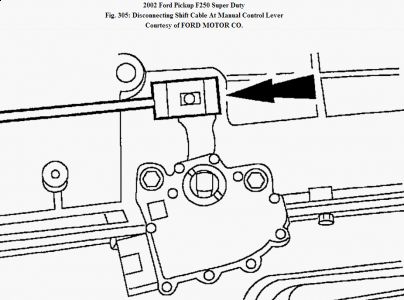
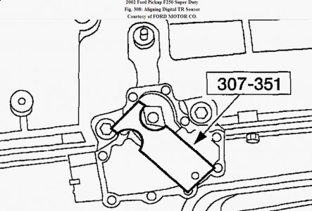
DIGITAL TRANSMISSION RANGE (TR) SENSOR Special Tool(s) Fig. 303: Identifying Special Tool Courtesy of FORD MOTOR CO. Removal 1. The customer needs to be notified that they may experience slightly different upshifts (either soft or firm) and that this is a temporary condition and will eventually return to normal operating condition. Disconnect the battery ground cable. For additional information, refer to BATTERY, MOUNTING AND CABLES . 2. Raise the vehicle on a hoist. 3. Disconnect the connector. Fig. 304: Disconnecting Connector Courtesy of FORD MOTOR CO. 4. Disconnect the shift cable at the manual control lever. Fig. 305: Disconnecting Shift Cable At Manual Control Lever Courtesy of FORD MOTOR CO. 5. Remove the digital transmission range (TR) sensor. 1. Remove the bolts. 2. Remove the digital transmission range (TR) sensor. Fig. 306: Removing Digital Transmission Range (TR) Sensor NOTE: If the vehicle is equipped with a power take-off unit, all or part of the PTO unit may need to be removed. NOTE: All gasoline vehicles will have new adaptive shift strategies. Whenever the vehicle's battery has been disconnected for any type of service or repair, the strategy parameters that are stored in the keep alive memory (KAM) will be lost. The strategy will start to relearn once the battery is reconnected and the vehicle is driven. This is a temporary condition and will return to normal operating condition once the powertrain control module (PCM) relearns all the parameters from the driving conditions. There is no set time frame for this process. If a concern is present during downshifts or converter clutch apply, it is not the fault of the shift strategy and will require diagnosis as outlined in the workshop manual.Courtesy of FORD MOTOR CO. Installation 1. Install the digital transmission range (TR) sensor. 1. Install digital transmission range (TR) sensor. 2. Loosely install the bolts. Fig. 307: Installing Digital Transmission Range (TR) Sensor Courtesy of FORD MOTOR CO. Fig. 308: Aligning Digital TR Sensor Courtesy of FORD MOTOR CO. 2. Using the special tool, align the digital TR sensor. The tool is designed to fit snug. 3. Tighten the bolts. Fig. 309: Identifying Tightening Torque Of TR Sensor Bolts Courtesy of FORD MOTOR CO. 4. Reconnect the shift cable at the manual control lever. Fig. 310: Connecting Shift Cable At Manual Control Lever Courtesy of FORD MOTOR CO. 5. Reconnect the connector. Fig. 311: Connecting Connector Courtesy of FORD MOTOR CO. 6. Lower the vehicle. 7. Reconnect the battery ground cable. NOTE: Make sure that the manual control lever is in the neutral position.
Friday, March 20th, 2009 AT 2:14 PM


