TEST B: ALL POWER DOOR LOCKS INOPERATIVE
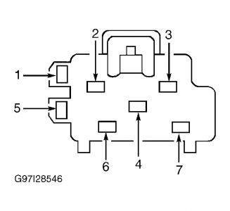
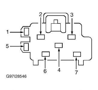
Turn ignition off. Disconnect right power door lock switch. Measure voltage between ground and door lock switch harness connector terminal No. 4 (Black/White wire). See Fig. 1 . If voltage is greater than 10 volts, go to next step. If voltage is not greater than 10 volts, repair Black/White wire. See WIRING DIAGRAMS . Retest system operation.
Ensure right power door lock switch is disconnected. Disconnect left front door lock actuator. Measure resistance between right door lock switch harness connector terminal No. 6 (Pink/Black wire) and left front door lock actuator harness connector circuit No. 117 (Pink/Black wire). If resistance is less than 5 ohms, go to next step. If resistance is not less than 5 ohms, repair Pink/Black wire. See WIRING DIAGRAMS . Retest system operation.
Ensure right door lock switch and left front door lock actuator are disconnected. Measure resistance between right door lock switch harness connector terminal No. 3 (Pink/Orange wire) and left front door lock actuator harness connector circuit No. 118 (Pink/Orange wire). If resistance is less than 5 ohms, go to next step. If resistance is not less than 5 ohms, repair Pink/Orange wire. See WIRING DIAGRAMS . Retest system operation.
Reconnect left front door lock actuator. Ensure right door lock switch is still disconnected. Disconnect left door lock switch. Measure resistance between left door lock switch harness connector terminal No. 6 (Pink/Yellow wire) and right door lock switch harness connector terminal No. 7 (Pink/Yellow wire). Measure resistance between left door lock switch harness connector terminal No. 3 (Pink/Light Green wire) and right door lock switch harness connector terminal No. 2 (Pink/Light Green wire). See Fig. 1 . If resistance is less than 5 ohms in either test, replace suspected door lock switch. Retest system operation. If resistance is not less than 5 ohms in either test, repair Pink/Yellow or Pink/Light Green wires. See WIRING DIAGRAMS . Retest system operation.
Fig. 1: Identifying Door Lock Switch Harness Connector Terminals

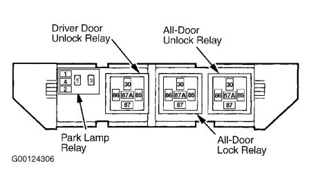
Check out the diagrams (Below). Please let us know what happens.
Image (Click to make bigger)
SPONSORED LINKS
Thursday, February 19th, 2009 AT 4:18 PM


