Hello -
Sorry so long to get back with you.........you did not come back across the server...........I found this another way.
First your codes........P0125 The condition and what you should check.
1. Continuous Memory DTC P0125: Check Engine Coolant Level
This DTC indicates ECT sensor has not reached the required temperature level to enter closed loop operating conditions within a specified amount of time after starting engine. Possible causes for this fault are:
"¢ Insufficient Engine Warm-Up Time
"¢ Thermostat Leaking Or Stuck Open
"¢ Malfunctioning CHT Or ECT Sensor
"¢ Low Coolant Level
P0304 has a lot of information but appears to be dealing with a misfire. I would first fix the P0125 and clear the codes and see if it returns.
The P1401 deals with your EGR system and you need a scanner to check it which only the dealer or possible a shop would be able to check.
As for the AC - the only way to really check it out to see what the problem is - is to use AC guage manifold set. As the instructions state below. You need to know the low and high side are doing as with that many miles it may be your compressor.
Many places charge a small fee to check your system out to tell you exactly what is wrong with it. That is the best way to check this.
If you open the system and change the orifice tube, you will need to pull a vacuum on the system to ensure all of the moisture is out or you may damage the system.
A/C SYSTEM PERFORMANCE
1. Park vehicle out of direct sunlight. Connect manifold gauge set. Start and run engine at 1500 RPM. Set A/C-heater selector switch to MAX A/C position.
2. Set blower motor on high speed, and close doors and windows. Insert thermometer in center vent. Operate system for 10 minutes to allow system to stabilize. Measure center vent output temperature. Center vent temperature will be 34-46 °F (1-8 °C) with ambient temperature of 60-90 °F (15.6-32.2 °C). See A/C SYSTEM TEMPERATURE SPECIFICATIONS table.
3. At about 68 °F (20 °C) ambient temperature, high side pressures should be approximately 100-200 psi (7.0-14.1 kg/cm2 ). Low side pressures should be approximately 22-47 psi (1.5-3.3 kg/cm2 ).
4. As low side pressure decreases, high pressure should increase. When A/C clutch disengages, low side pressure will increase and high side pressure should decrease. See A/C SYSTEM HIGH SIDE PRESSURE SPECIFICATIONS table. Low side pressure remains constant throughout normal operating range.
I am giving you the info but you also need an extraction tool for the orifice.
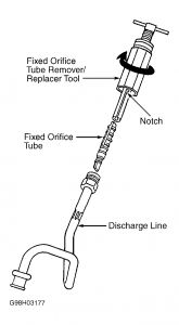
FIXED ORIFICE TUBE
Removal & Installation
1. Discharge A/C system, using approved refrigerant recovery/recycling equipment. Pull back protective cover. Place index marks on condenser-to-evaporator line. Disconnect condenser-to-evaporator line. Cap openings.
2. Pour small amount of clean refrigerant oil into outlet end of discharge line to lubricate tube and "O" rings for removal. Using Fixed Orifice Tube Remover/Replacer (T83L-19990-A), engage 2 tangs on orifice tube. Do not twist or rotate orifice tube.
3. Hold "T" handle of tool, then turn nut down against discharge line until fixed orifice tube is pulled from discharge line. See Fig. 15 . To install, reverse removal procedure. Use new "O" rings coated with new refrigerant oil.
NOTE: If fixed orifice tube breaks inside discharge line, it can be removed with Broken Orifice Tube Extractor (T83L-19990-B).
I hope this helps.
May 31, 2010 at 7:51 PM
