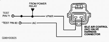
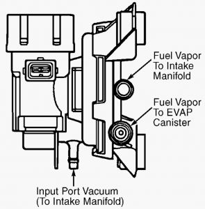
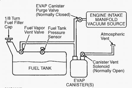
Air leaks(vacuum) is the probable cause! Use a can of spray TBI cleaner and spray around, when you find a leak the engine idle will change. 20) DTC P1506 This DTC indicates IAC system has reached over speed malfunction. Possible causes are: Ã Â Â IAC circuit short to ground. Ã Â Â IAC assembly stuck open. Ã Â Â Air intake leaks or restrictions. Ã Â Â Damaged throttle body. Ã Â Â Contaminated or damaged IAC valve assembly. Ã Â Â Faulty Powertrain Control Module (PCM). Start engine and allow to idle. Inspect air inlet system any of the following possible faults: Ã Â Â Cracked or punctured air inlet tube. Ã Â Â Loose inlet air tube or air cleaner housing. Ã Â Â Loose or damaged throttle body. Ã Â Â Contaminated or damaged IAC valve assembly. Ã Â Â Faulty EGR valve or gasket. Ã Â Â Faulty PCV valve or hose. Check entire system for vacuum leaks. Repair as necessary. If no vacuum leaks are found, go to next step. 21) Check EVAP System Turn ignition off. Disconnect hoses from EVAP canister purge valve. Connect a vacuum pump to carbon canister hose port. See Fig. 53 . Using vacuum pump, apply 16 in. Hg to port. If vacuum bleeds off within 20 seconds, replace EVAP canister purge valve. If vacuum holds, go to next step. Fig. 53: Identifying EVAP Canister Purge Hose Ports 22) Check IAC Valve Function Start engine and allow to idle. Ensure transmission is in Park or Neutral and engine is warmed to normal operating temperature. Disconnect IAC valve wiring harness connector. If engine speed drops, go to next step. If engine speed does not drop, check throttle body for damage. If throttle body is okay, replace IAC valve. 23) Check IAC Circuit For Short To Ground Turn ignition off. Disconnect scan tool from DLC. Disconnect PCM 104-pin connector. Inspect connector for loose, damaged or corroded terminals. Repair as necessary. Install Breakout Box (014-00950), leaving PCM disconnected. Measure resistance between test pin No. 83 (IAC) and test pins No. 51 and 103 (PWR GND) at breakout box. If both resistance readings are more than 10,000 ohms and idle speed is normal, go to step 30). If both resistance readings are more than 10,000 ohms and high idle speed is present, replace PCM. If resistance is 10,000 ohms or less, repair short to ground in IAC circuit.
9/22/2009 ...


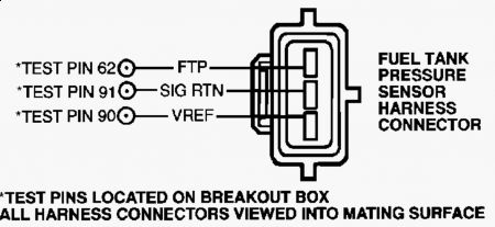
33) DTC P0453: Check FTP Sensor Voltage Turn ignition on. Using scan tool, select FTP V PID. If PID voltage is more than 4.5 volts, go to next step. If voltage is 4.5 volts or less, fault is intermittent. Go to step 42). 34) Check For Short To Power Turn ignition off. Disconnect FTP sensor connector, located on top of fuel tank. Turn ignition on. Measure voltage between FTP terminal at FTP sensor wiring harness connector and negative battery terminal. If voltage is 10.5 volts or less, go to step 36). If voltage is more than 10.5 volts, go to next step. 35) Check FTP Circuit For Short To VPWR Circuit Turn ignition off. Disconnect PCM 104-pin connector. Inspect connector for loose, damaged or corroded terminals. Install Breakout Box (014-00950), leaving PCM disconnected. Turn ignition on. Measure voltage between test pins No. 62 and 103 at breakout box. If voltage is more than 10.5 volts, repair short circuit. If voltage is 10.5 volts or less, replace PCM. 36) Check Opposite Induced Low FTP Signal Turn ignition off. Connect a jumper wire between SIG RTN and FTP terminals at FTP sensor wiring harness connector. Turn ignition on. If scan tool communication link error is displayed, remove jumper wire and go to step 41). Using scan tool, select FTP V PID. If PID voltage is less than .1 volt, remove jumper wire and go to next step. If PID voltage is .1 volt or more, unable to induce opposite signal. Go to step 39). 37) Check Voltage At FTP Sensor Connector Measure voltage between VREF and SIG RTN terminals at FTP sensor wiring harness connector. If voltage is 4-6 volts, go to next step. If voltage is not 4-6 volts, VREF voltage is out of range. Go to CIRCUIT TEST C . 38) Check For Short Circuit Turn ignition off. Disconnect PCM 104-pin connector. Inspect connector for loose, damaged or corroded terminals. Install Breakout Box (014-00950), leaving PCM disconnected. Measure resistance between test pins No. 62 and 90 at breakout box. If resistance is more than 10,000 ohms, replace FTP sensor. If resistance is 10,000 ohms or less, repair FTP circuit short to VREF circuit. 39) Check For Open FTP Circuit Turn ignition off. Disconnect PCM 104-pin connector. Inspect connector for loose, damaged or corroded terminals. Install Breakout Box (014-00950), leaving PCM disconnected. Measure resistance between test pin No. 62 at breakout box and FTP terminal at FTP sensor wiring harness connector. If resistance is less than 5 ohms, go to next step. If resistance is 5 ohms or more, repair open in FTP circuit. 40) Check For Open SIG RTN Circuit Measure resistance between test pin No. 91 at breakout box and SIG RTN terminal at FTP sensor wiring harness connector. If resistance is less than 5 ohms, go to next step. If resistance is 5 ohms or more, repair open in SIG RTN circuit. 41) Check FTP Circuit For Short To VREF Circuit Measure resistance between test pins No. 62 and 90 at breakout box. If resistance is more than 10,000 ohms, replace PCM. If resistance is 10,000 ohms or less, repair FTP circuit short to VREF circuit. 42) Check For Intermittent Open Or Short To Power Turn ignition on. Using scan tool, select FTP V PID. Observe FTP V PID for indication of fault while shaking and bending FTP sensor wiring harness and connector. A fault will be indicated by a sudden change in FTP V PID voltage. Tap lightly on sides of FTP sensor to simulate road shock. DO NOT tap on top of sensor. If fault is indicated, isolate fault and repair as necessary. If no fault is indicated, go to CIRCUIT TEST Z . NOTE: A break in step numbering sequence occurs at this point. Procedure skips from step 42) to step 44). No test procedures have been omitted.


Tuesday, September 22nd, 2009 AT 4:16 PM


