So here goes.
Removal (Bronco & F150 4WD W/Automatic & Manual Locking Hubs, F250, F250 H.D. & F350 4WD
W/Manual Locking Hubs)
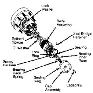
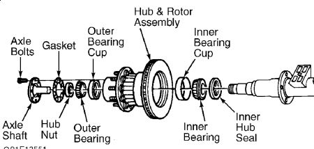
1.Raise vehicle, and support with safety stands. Remove wheel assembly and caliper. On Bronco and F150 Series with automatic locking hubs, separate hub cap from hub body assembly by removing 5 Torx (TX25) head cap screws. See Fig. 16. Remove cap. DO NOT drop spring,
6/5/2009
Page 17 of 29
ball bearing, bearing race or retainer.
NOTE: Information for rotor removal on F250/F350 with automatic locking hubs is not available from manufacturer. Procedure should be similar to other locking hub procedures.
Fig. 16: Removing Front Rotor (4WD Bronco & "F" Series) Courtesy of FORD MOTOR CO.
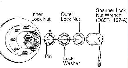
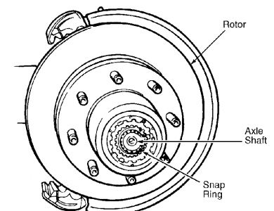
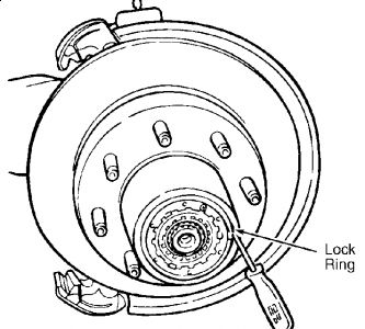
2.Remove rubber seal and seal bridge from retainer ring space. Remove retainer ring by squeezing ends together. Remove hub body assembly. Remove "C" washer and splined spacer from spindle. On Bronco and "F" Series with manual locking hubs, separate hub cap from hub body assembly by removing 6 Allen head screws. 3.Remove snap ring attaching hub body assembly to spindle. Remove lock ring seated in groove of hub. See Fig. 17. Remove hub body assembly. If hub body does not come out easily, install 2 hub cap screws into hub body, and pull hub body out of hub. 4.On Bronco and F150 with automatic locking hubs and on F250 Heavy Duty and F350 with manual locking hubs, use Spanner Lock Nut Wrench (D85T-1197-A) to remove outer lock nut. See Fig. 18. Remove lock washer. Using Spanner Lock Nut Wrench (D85T-1197-A), remove inner lock nut. Remove outer wheel bearing and rotor. 5.On Bronco and F150/F250 Light Duty with manual locking hubs, use Spanner Lock Nut Wrench (T86T-1197-A) to remove wheel bearing adjusting nut. Remove outer wheel bearing, and then rotor.
Fig. 17: Removing Front Hub (4WD Bronco & "F" Series) Courtesy of FORD MOTOR CO.
Fig. 18: Removing Outer Lock Nut (Bronco & F150 W/Auto Locking Hubs, F250 H.D. & F350 W/Manual Locking Hubs)
Installation
1.On Bronco and F150 with automatic locking hubs and on F250 Heavy Duty and F350 with manual locking hubs, install rotor and outer wheel bearing. Install inner lock nut. While rotating disc back and forth, seat bearing by using Spanner Lock Nut Wrench (D85T-1197-A) to tighten inner lock nut to 50 ft. lbs. (68 N.m). Back off inner lock nut, and retighten to 30-40 ft. lbs. (41-54 N.m). 2.Install lock washer so key is in spindle groove. Tighten inner lock nut to engage lock nut pin in nearest lock washer hole. Install outer lock nut, and tighten to 160-205 ft. lbs. (217-278 N.m). Spindle end play should be less than .004" (.10 mm). 3.On Bronco and F150/250 Light Duty with manual locking hubs, install rotor and outer wheel bearing. Install adjusting nut. While rotating disc back and forth, seat bearing by using Spanner Lock Nut Wrench (T86T-1197-A) to tighten adjusting nut to 70 ft. lbs. (95 N.m). 4.Back off adjusting nut 90 degrees, and retighten to 15-20 ft. lbs. (20-27 N.m). Spindle end play should be zero. To install remaining hub body components, reverse removal procedure. See Fig. 16.
Tuesday, April 6th, 2021 AT 12:09 PM


