The EI system consists of a Crankshaft Position (CKP) sensor, coil pack(s), related wiring and PCM. The CKP sensor is used by the PCM to indicate crankshaft position and speed by sensing a missing tooth on a pulse wheel mounted on front of crankshaft. The coil pack receives the signal from the PCM to fire at a calculated spark target. Each coil within the pack fires 2 spark plugs at the same time.
The plugs are paired so one plug is fired on the compression stroke, and the other plug fires the mating cylinder, which is on the exhaust stroke. On the next cycle, firing strategy is reversed. On 6-tower coil pack applications the matched cylinder pairs are: No. 1 and 5, No. 2 and 6, and No. 3 and 4. See Fig. 18 and Fig. 19 .
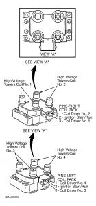
On dual 4-tower coil pack applications (8 cylinder), the matched cylinder pairs are No. 1 and 6, No. 3 and 5, No. 4 and 7, and No. 2 and 8. See Fig. 20 . On single 4-tower coil pack applications (4 cylinder), the matched cylinder pairs are No. 1 and 4, and No. 2 and 3. See Fig. 20 .
The PCM acts as an electronic switch to ground in the coil primary circuit. When the switch is closed, positive battery voltage applied to the coil primary circuit builds a magnetic field around the primary coil. When the switch opens, power is interrupted and the primary field collapses inducing high voltage in the secondary coil winding and the spark plug is fired.
Fig. 18: Six Tower Coil Pack 6-Cylinder Identification - 2.5L, 3.0L (2V), 3.8L & 4.2L
Courtesy of FORD MOTOR CO.
Fig. 19: Six Tower Coil Pack 6-Cylinder Identification - 4.0L (2V) & 4.0L (DOHC)
Courtesy of FORD MOTOR CO.
Fig. 20: Four Tower Coil Pack 4 & 8-Cylinder Identification - 2.0L (SOHC), 2.0L (DOHC), 2.5L & 5.0L
Courtesy of FORD MOTOR CO.
Models Equipped With Coil On Plugs (COPs)
The EI system consists of a Crankshaft Position (CKP) sensor, Camshaft Position (CMP) sensor, individual COPs, related wiring and PCM. Individual COPs are mounted directly on the spark plugs. See Fig. 7 . The CKP sensor is used by the PCM to indicate crankshaft position and speed by sensing a missing tooth on a pulse wheel mounted on front of crankshaft. The CMP sensor is used by the PCM to identify when piston No. 1 is at Top Dead Center (TDC) of compression stroke. This signal is used to synchronize firing of individual coils.
The individual coils receive their signal from the PCM to fire at a calculated spark target. Only one coil is fired at a time and only on the compression stroke. The PCM acts as an electronic switch to ground the individual coil primary circuit. When the switch is closed, battery voltage applied to the coil primary circuit builds a magnetic field around the primary coil. When the switch opens, power is interrupted and the primary field collapses, inducing high voltage in the secondary coil winding and the spark plug is fired.

Wednesday, January 14th, 2009 AT 8:56 PM


