Hi,
Try this and let us know what happens: Place the transmission in gear and see if you can move the car without the engine turning. If you still hear the clicking and the vehicle feels like it is in neutral, the axle isn't fully inserted into the transmission.
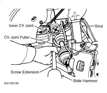
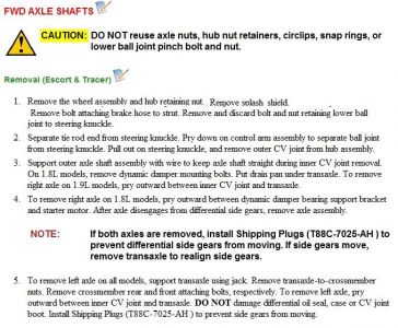
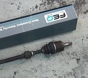
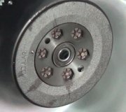
Here are the directions from A to Z for axle replacement. Take a look through it and see if anything was missed, including specifically when it comes to the install of the axle. All of the pictures correlate with the directions.
____________________________________________________
1998 Ford Escort L4-122 2.0L SOHC
Removal and Installation
Vehicle Transmission and Drivetrain Drive Axles, Bearings and Joints Axle Shaft Assembly Axle Shaft Service and Repair Procedures Axle Shaft Assembly, Constant Velocity Type Halfshaft Removal and Installation
REMOVAL AND INSTALLATION
pic 1
REMOVAL
1. Raise and support the vehicle.
Pic 2
2. Remove the front tire and wheel.
1 Remove the lug nuts.
2 Remove the front tire and wheel.
NOTE: LH shown, RH similar.
Pic 3
3. Raise the staked portion of the front axle wheel hub retainer using a small cape chisel.
Pic 4
4. Remove and discard the front axle wheel hub retainer.
Pic 5
5. Remove the cotter pin and the tie rod end nut.
Pic 6
6. Use Tie Rod End Remover to separate the (A) tie rod end from the (B) front wheel knuckle.
Pic 7
7. Remove the stabilizer bar link.
1 Remove the front stabilizer bar end nut.
2 Remove the front stabilizer bar end bolt.
3 Remove the upper front stabilizer bar end retainer.
4 Remove the front stabilizer bar end bushing above the front stabilizer bar.
5 Remove the front stabilizer bar end bushing below the front stabilizer bar.
6 Remove the front stabilizer bar end bushing.
7 Remove the front stabilizer bar end bushing above the front sub-frame.
8 Remove the front stabilizer bar end bushing below the front sub-frame.
9 Remove the lower front stabilizer bar end retainer.
Pic 8
8. Remove the nut and the ball joint pinch bolt.
Pic 9
9. Pry down on the (A) front suspension lower arm separating the (B) front suspension lower arm ball joint from the (C) front wheel knuckle.
Pic 10
10. Pull outward on the (A) front wheel knuckle then pull the (B) front wheel driveshaft and joint from the front wheel knuckle.
Pic 11
11. If removing the LH front wheel driveshaft and joint, remove the crossmember to access the front wheel driveshaft and joint.
Pic 12
12. If removing the RH front wheel driveshaft and joint, remove the RH side shield.
1 Remove the RH side shield bolts.
2 Remove the RH side shield.
Pic 13
13. If removing the RH front wheel driveshaft and joint, remove the RH splash shield.
1 Remove the RH splash shield bolts.
2 Remove the RH splash shield.
Pic 14
14. If removing the LH front wheel driveshaft and joint, insert a pry bar between the front wheel driveshaft and joint and the transaxle case and pry outward, releasing the front wheel driveshaft and joint from the differential side gears.
CAUTION: Extreme care must be taken to ensure that the pry bar does not damage the transaxle case, the transaxle oil seal, the front wheel driveshaft and the joint and joint boot.
Pic 15
15. If removing the Coupe M/T RH front wheel driveshaft and joint, remove the bolts from the center support bearing.
Pic 16
16. Lower the Coupe M/T driveshaft assembly and remove the halfshaft from the differential side gears.
Pic 17
17. Separate the Coupe M/T front wheel driveshaft and joint from the center support bearing and the halfshaft.
Inspect the center support bearing and the halfshaft; replace if necessary.
Pic 18
18. Install Transaxle Plugs if both front wheel driveshaft and joints are removed.
INSTALLATION
pic 19
1. If equipped, install a new driveshaft bearing retainer circlip.
Pic 20
2. Remove the transaxle plugs if necessary.
Pic 21
3. Position the front wheel driveshaft and joint so the splines line up with the differential side gear splines. Push the front wheel driveshaft and joint into the differential side gear.
NOTE: When seated properly, the driveshaft bearing retainer circlip can be felt as it snaps into the differential side gear groove.
Pic 22
4. If installing the Coupe RH driveshaft and joint with M/T, position the front wheel driveshaft and joint so that the splines line up with the splines in the halfshaft, and push the front wheel driveshaft and joint and the halfshaft together with the center support bearing.
Pic 23
5. Position the Coupe M/T driveshaft assembly and push into the differential side gears.
Pic 24
6. Position the Coupe M/T center support bearing and install the bolts.
Pic 25
7. If installing the RH front wheel driveshaft and joint, install the RH side shield.
1 Position the RH side shield.
2 Install the RH side shield bolts.
Pic 26
8. If installing the RH front wheel driveshaft and joint, install the RH splash shield.
1 Position the RH splash shield.
2 Install the RH splash shield bolts.
Pic 27
9. Pull outward on the (A) front wheel knuckle and insert the (B) front wheel driveshaft and joint into the front wheel knuckle.
Pic 28
10. Pry down on the (A) front suspension lower arm, then install the (B) front suspension lower arm ball joint into the (C) front wheel knuckle.
Pic 29
11. Position the crossmember and install the bolts.
Pic 30
12. Install the ball joint pinch bolt and nut.
Pic 31
13. Install the stabilizer bar link and tighten the bar end nut to the protruding bar end bolt length specification.
Pic 32
14. Position the tie rod end to the front wheel knuckle and install the tie rod end nut and a new cotter pin.
NOTE: If the slot in the nut is not aligned to the hole, tighten the nut as necessary to align.
Pic 33
15. Install a new front axle wheel hub retainer.
Pic 34
16. Stake the front axle wheel hub retainer (the minimum specification is shown).
CAUTION: If the front axle wheel hub retainer splits or cracks after staking, replace it.
Pic 35
17. Install the front wheel and tire.
1 Install the front tire and wheel.
2 Install the lug nuts.
3 Tighten the lug nuts in sequence.
18. Check and refill the transmission fluid.
Images (Click to make bigger)
Wednesday, October 7th, 2020 AT 11:50 AM
(Merged)


