GENERAL INSPECTION
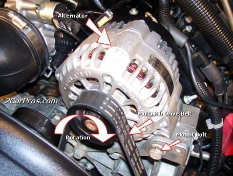
Ensure battery posts and cables are clean and tight. Check drive belt tension. Ensure connections at alternator, regulator and engine ground are clean and tight. Check fusible links and replace as necessary.
Turn ignition on and ensure charge warning light operates. Check bulb and circuit if necessary. Start engine and verify charge warning light goes out. If warning light goes out, see AMPERAGE OUTPUT TEST . If warning light does not go out, see VOLTAGE OUTPUT TEST. There are 4 conditions that can cause charge indicator light to come on:
No Alternator Output
Overcharging
Alternator Output Wire Open
Voltage Sensing Wire (Terminal "A" circuit) Open
Check 100-amp main fuse, 30-amp fuel injection fuse located in engine compartment fuse box. Check 15-amp meter fuse located in passenger compartment fuse box.
AMPERAGE OUTPUT TEST
Ensure drive belt is in good condition and properly tightened. Connect charging system load tester in accordance with manufacturer's instructions. Start and run engine at 2500-3000 RPM and apply load until alternator output levels off.
Record maximum alternator output current. See ALTERNATOR OUTPUT SPECIFICATIONS table for output values. If alternator output is within 20% of rated output amperage, alternator output is okay. If alternator does not produce rated output, go to VOLTAGE OUTPUT TEST.
ALTERNATOR OUTPUT SPECIFICATIONS
ApplicationAmps Rating
Escort65
VOLTAGE OUTPUT TEST
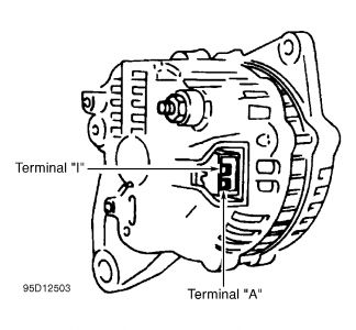
NOTE:On some alternators, terminal "A" may be identified as terminal "S", and terminal "I" may be identified as terminal "L".
Ensure battery is fully charged. Turn ignition switch to RUN position and leave engine off. Battery voltage should be present at terminals "B+" and "A" at alternator connector. See Fig. 1 . Approximately one volt should be present at terminal "I". If voltages are correct, go to next step. If voltages are not correct go to step 3).
Start engine and run at 2000 RPM. With alternator connected, check voltage at terminals "B+", "A" and "I". At terminals "B+" and "A", 14.1-14.7 volts should be present. At terminal "I", 13-14 volts should be present (engine running). If voltages are not correct, go to next step. If voltages are correct, go to step 4).
Check 100-amp MAIN fuse and 30-amp FUEL INJ fuse. Check all fuses and fusible links. If fuses are okay, test "B+", "A" and "I" circuits for opens, shorts and excessive resistance. Repair as necessary. If okay, go to next step.
Perform voltage drop test on "B+" circuit (between positive battery and terminal "B+" on alternator). If voltage drops .5 volt or more, repair wire between terminal "B+" and positive battery. If voltage is still not correct, repair or replace alternator.

Friday, December 12th, 2008 AT 12:06 PM


