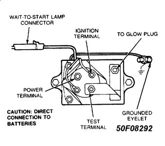
Check wiring and connections of glow plug controller
SYSTEM OVERVIEW
The solid state glow plug system consists of the glow plug controller (mounted on rear of intake manifold), glow plug harness assembly, and glow plugs. The system determines glow plug temperature by electronically measuring the resistance of glow plugs. It then maintains this temperature regardless of ambient temperature.
The afterglow operation of the glow plugs continues after the "WAIT TO START" light turns off. The glow plugs cycle on and off for a period of time. This helps reduce white smoke after engine start-up. The system can be recycled by turning ignition off and on. The engine can be started as soon as the "WAIT TO START" light goes off.
GLOW PLUG DESCRIPTION
The system uses positive temperature coefficient (PTC) glow plugs. The resistance of the glow plugs changes as the temperature rises. The glow plugs use bullet type terminals. GLOW PLUG CONTROLLER DESCRIPTION
The power relay is mounted on top of the solid-state controller circuit board. The complete assembly is mounted on the rear of the intake manifold.

Thursday, March 25th, 2010 AT 5:58 AM


