Hello ..thanks for the donation .. much appreciated
Hope this helps !
INTAKE MANIFOLD
Removal
Disconnect negative battery cable. Release fuel pressure and disconnect fuel lines. See FUEL PRESSURE RELEASE & FUEL LINE CONNECTIONS. Remove fan blade, fan clutch and fan shroud.
Drain cooling system. Remove air intake tubing. Remove wiper motor. Release belt tensioner, and remove accessory drive belt. Disconnect spark plug wires at spark plugs.
Disconnect spark plug wires from valve cover studs. Disconnect wiring from both ignition coils. Disconnect Camshaft Position (CMP) sensor connector. CMP is located in top left side of engine front cover.
Remove 4 ignition wire tray-to-ignition coil bracket bolts. Remove spark plug wire assembly from above intake manifold. Disconnect generator wiring harness from junction block, fender apron and generator.
Remove generator brace-to-intake manifold bolts. Remove alternator-to-cylinder block bolts. Remove generator. Raise and support vehicle.
Disconnect oil pressure sending unit and power steering control valve. Position wiring harness aside. Remove EGR manifold tube.
Lower vehicle. Disconnect control cables from throttle body. On Crown Victoria, Grand Marquis and Town Car, remove 42-pin wiring harness connector from retaining bracket on vacuum booster, and disconnect connector. On all models, disconnect wiring harness connectors, coolant hoses, and vacuum hoses as necessary. Remove PCV valve from valve cover. Disconnect canister purge vent hose from PCV valve and control cables from throttle body.
CAUTION:Thermostat housing bolts are also used to retain intake manifold.
Remove accelerator cable bracket from intake manifold, and secure aside. Remove thermostat housing retaining bolts. Remove thermostat housing with upper radiator hose attached, and secure aside.
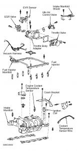
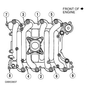
Remove intake manifold retaining bolts in reverse order of tightening sequence. See Fig. 5 Remove intake manifold and gaskets. Fig. 4 . If removing fuel rail and fuel injectors, remove fuel rail retaining bolts. Lift fuel rail and fuel injectors from intake manifold.
Installation
To install, reverse removal procedure. Use NEW gaskets and "O" rings. Lubricate fuel injector "O" rings with Light Grade Oil (ESE-M2C39-F) before installing.
CAUTION:Intake manifold bolts must be retightened to specification after engine has reached normal operating temperature.
Ensure alignment tabs on intake manifold gaskets align with holes in cylinder head. Tighten intake manifold bolts to specification in sequence. See Fig. 5 When installing fuel lines, fit NEW fuel resistant "O" rings (Brown) on fuel lines. Lightly coat "O" rings with clean engine oil before installing. Clean fittings, and replace garter spring (if necessary).
To install remaining components, reverse removal procedure. Adjust all control cables and fluid levels. Refill cooling system. When installing spark plug wires, ensure wires are in correct position on coils.
Fig. 3: Exploded View Of Intake Manifold Assembly - Gasoline Engine

Fig. 5: Intake Manifold Bolt Tightening Sequence - Gasoline Engine

SPONSORED LINKS
Tuesday, February 10th, 2009 AT 1:02 PM


