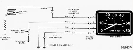
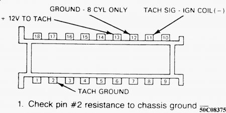
TACHOMETER TESTING The tachometer can be used on either 6-cylinder or V8 engines. Tachometer terminals "B" (12 volts), "C" (coil negative) and "G" (ground) are connected when used on 6-cylinder engines. A fourth terminal "8" (V8 ground) is grounded through wiring harness for V8 operation. See Fig. 2 . 1. Fig. 2: Tachometer Wiring Diagram Courtesy of FORD MOTOR CO. Check fuse, replace if blown. Check for loose wiring connections in engine compartment or at instrument cluster. Secure where necessary. Disconnect negative battery cable. Remove instrument cluster. See Instrument Cluster R & I section in this article. Make resistance and voltage checks using a VOM. 2. Check pin No. 2 for resistance to ground. Reading should be one ohm or less. See Fig. 3 . Check pin No. 12 for resistance to ground for V8 or open circuit for 6-cylinder. Reading should be one ohm or less. 3. Fig. 3: Testing Tachometer Circuits Courtesy of FORD MOTOR CO. Check pin No. 11 for resistance to negative terminal of ignition coil. Reading should be one ohm or less. Connect battery and turn ignition on. Check for 12 volts at pin No. 13. Turn ignition off. Disconnect battery. 4. If readings are not okay, problem is not in tachometer. Service wiring. If readings are okay, check for loose or missing cluster connection clips. Check for damaged printed circuit. Reseat or replace missing clips. Replace printed circuit as necessary. If connection clips and printed circuit are okay, replace tachometer. See appropriate chassis wiring diagram in the WIRING DIAGRAMS section. 5. Page 1 of 1 INSTRUMENT PANEL - STANDARD -1987 Ford Bronco 5/17/2009


SPONSORED LINKS
Sunday, May 17th, 2009 AT 7:33 AM


