Ignition switches don't care about reversed polarity. You are likely right that there's no voltage on any fuses, but that points even more strongly to the fuse link wires.
Your ignition switch is mounted on the top or right side of the steering column, under the dash. It has multiple sections, so even if part of it had a burned or pitted contact, something would still work. Most common for all ignition switches is the section that turns on the accessory circuit fails first, to include melted terminals in the connector body. This circuit has the most stress on it, especially when people turn the switch on and off while the heater fan motor switch is on one of the higher speed settings. That forces that part of the ignition switch to turn that high current on and off, and that causes internal sparks and arcing that leads to the switch failure.
Also, with your switch design, it is mounted with two small screws, and the mounting holes are slotted to allow for adjustment. It is not uncommon for the screws to work loose, then the switch gets out-of-adjustment. The symptom typically is the dash lights will turn on, but you can't turn the switch far enough for the starter to engage. This is not related to reversed polarity.
If you look back at the diagrams, at a minimum, fuses 1, 8, and 12 should be hot all the time. Fuse 1 is fed from the top fuse link wire with my yellow arrow. Fuses 4, 8, 12, and 16 are fed from the other fuse link with the orange arrow. I don't see anything else in there. As I mentioned previously, more than one of us has left those wires off the solenoid by mistake, so double-check they're all connected.
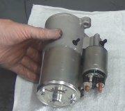
I should mention too that Ford had at least three versions of starter solenoid that all looked the same, but they aren't interchangeable. The two fat terminals for the starter current are the same on all versions. It's the smaller two that are different. The one that comes from the ignition switch, usually red with a blue stripe, is also the same. The difference has to do with the second smaller terminal On some versions that has to get grounded by the neutral safety switch before the solenoid will energize. On others, the neutral safety switch is in the red / blue wire circuit, then the second terminal is for the ignition ballast resistor bypass during cranking, for easier starting.
Fuse link wires can be purchased at any auto parts store. They're selected by color, just like with regular fuses, to indicate their current rating. Don't use regular wire for replacements. The insulation on fuse link wires is designed to not burn or melt. The wire itself is a smaller diameter than the wires in the circuits they protect, to be the "weak-link-in-the-chain". The new wire will be about 12" long. It can be cut into three of four pieces to make multiple repairs. It's actual length in the circuit is not important.
Solder the splices, then seal them with moisture-proof heat-shrink tubing. You can find that at the auto parts stores too. Don't use electrical tape. It will unravel into a gooey mess on a hot day.
Getting back to your voltage measurements, check right across the battery terminals too. That will insure your test light is working. You wouldn't believe how many times I went the wrong direction when trying to diagnose a tv problem because I didn't have my meter set correctly. Next, leave the probe on the battery's positive terminal, but move the ground clip to a paint-free point on the body sheet metal. If the test light doesn't turn on there, check the smaller negative battery wire. That one gets bolted to the body. Everything will be dead if that one is left off or corroded.
Image (Click to make bigger)
Tuesday, December 22nd, 2020 AT 2:33 PM


