Hello -
Great job and thanks for the info. . .. . .. . .the code is kind of what I have. . .. . .
CODE 35
DRB displays RADIATOR FAN RELAY CTRL CIRCUIT. Condition is: open or shorted condition detected in radiator fan relay circuit.
If you don't mind to be safe how about putting it all back together and clear the codes and then try it again. . .. . .. . ..that way we are not chasing rabbits. . .. . .. . .
Then we will pull some more tests. I have attached them below.
OPERATION
OPERATION
Radiator fan operates when coolant temperature sensor verifies coolant temperature has reached predetermined temperature (depending on model). On reaching specified temperature, coolant temperature sensor contacts close, allowing current flow to radiator fan relay and fan motor. Fan shuts off when coolant temperature drops to predetermined value (depending on model).
Radiator fan should always operate when A/C compressor clutch is engaged. On models with dual electric fans, fans operate through a common relay and are activated at the same time.
SYSTEM TESTING
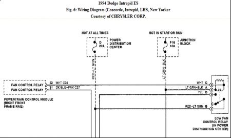
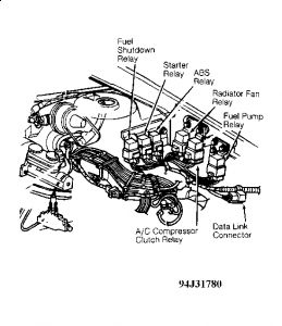
1. Check fan motor operation. See MOTOR under COMPONENT TESTING. If motor is okay, turn ignition on and check for voltage at fan relay Gray (or Light Green/Black) wire. Radiator fan relay may be located in power distribution center (left front inner fender panel) or in front of left strut tower. See Fig. 1 . If battery voltage exists, proceed to next step. If battery voltage does not exist, check for open or short in Gray (or Light Green/Black) wire circuit.
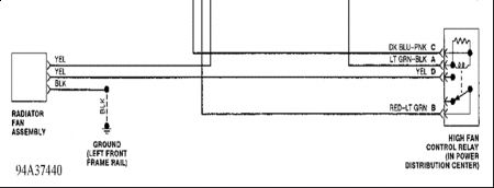
2. Install jumper wire between Gray (or Light Green/Black) and Light Green (or Dark Blue/Pink) wires on radiator fan relay. If fan operates, proceed to next step. If fan fails to operate, check for open or short in Light Green (or Dark Blue/Pink) wire between radiator fan relay and fan relay motor connector.
3. If fan operates, warm engine to normal operating temperature. Check for loose connections on fan motor and at fan motor relay. If all connections are okay, check for fault codes.
4. Fault codes can be checked by using diagnostic connector, located in front of left shock tower. Refer to appropriate SELF-DIAGNOSTICS article in ENGINE PERFORMANCE for complete instructions on connecting diagnostic connector and checking for fault codes. After checking fault codes, see COMPONENT TESTING . Repair as necessary.
MOTOR
Concorde, Intrepid, LHS, New Yorker & Vision
1. Disconnect electric fan motor. Connect 12-volt battery negative lead to electric fan motor Black wire connector terminal. Connect battery positive lead to electric fan motor Tan wire connector terminal. Fan motor should operate at low speed.
2. Connect positive lead to electric fan motor Yellow wire connector terminal. Fan motor should operate at high speed. Replace electric fan motor if it fails to operate properly.
1.
CAUTION: Check electric fan motor operation before checking fan relay and PCM. Ensure PCM is securely grounded.
RELAY
Concorde, Intrepid, LHS, New Yorker & Vision
1. Check for loose connections on fan motor and at fan motor relay. If all connections are okay, fault codes must be checked. If no fault codes are present, go to next step.
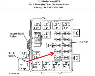
2. With ignition on and engine at normal operating temperature, check for battery voltage on both sides of cooling fan relay fuse. Cooling fan relay fuse and high and low speed fan relays are located in fuse/relay box in front of left strut tower. See Fig. 2 .

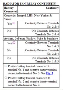
3. If battery voltage is not present, repair short or open in Red/Light Green wire circuit. If battery voltage is present, remove low speed or high speed fan motor relay. Using an ohmmeter, ensure continuity exists between terminals No. 1 and 3. See Fig. 3 . If continuity does not exist, replace relay.
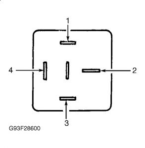
4. Connect ohmmeter to relay terminals No. 2 and 4. Check continuity with and without battery connected. See RADIATOR FAN RELAY CONTINUITY table. Replace relay if continuity is not as specified.
Let me know what you find out
Wednesday, August 19th, 2009 AT 12:06 AM


