If it wont work with either switch, but does with the remotes, check the driver's door module. DRBIII scan tool is needed to do this.
Preliminary Tests To begin this test, note the system operation while you actuate both the Lock and Unlock functions with the power lock switches, the door cylinder lock switches (if equipped with the optional Vehicle Theft Security System (VTSS), and the RKE transmitter. Then, proceed as follows: � � � If the entire power lock system fails to function with the power lock switches, the door cylinder lock switches, or the RKE transmitter, check the Fused B+ fuse in the Junction Block (JB). If the fuse is okay, proceed to the diagnosis of the power lock motors. See DOOR LOCK MOTOR under COMPONENT TESTS. � � � If the power lock system functions with both power lock switches, and both the door cylinder lock switches, but not with the RKE transmitter, proceed to the diagnosis of the RKE transmitter. See REMOTE KEYLESS ENTRY TRANSMITTER under COMPONENT TESTS. � � � If the entire power lock system functions with the RKE transmitter, and both door cylinder lock switches, but not with one or both of the power lock switches, proceed to diagnosis of the Driver Door Module (DDM) for the driver side switch or to diagnosis of power lock switch for the passenger side switch. See DRIVER DOOR LOCK SWITCH and/or PASSENGER DOOR LOCK SWITCH under COMPONENT TESTS. � � � If the entire power lock system functions with the RKE transmitter, and both power lock switches, but not with one or both of the door cylinder lock switches, proceed to diagnosis of the door cylinder lock switches. See DOOR CYLINDER LOCK SWITCH under COMPONENT TESTS. � � � If one power lock motor fails to operate with both of the power lock switches, both of the door cylinder lock switches, and/or the RKE transmitter, proceed to diagnosis of the power lock motor. See DOOR LOCK MOTOR under COMPONENT TESTS. � � � If the problem being diagnosed is related to one or more of the electronic features (automatic locks, driver door unlock only, door lock inhibit, enhanced accident response, illuminated entry, panic mode, RKE horn chirp, or RKE optical chirp), further diagnosis should be performed using a DRBIII � scan tool. See BODY CONTROL MODULES - DAKOTA article.Test switch this way.
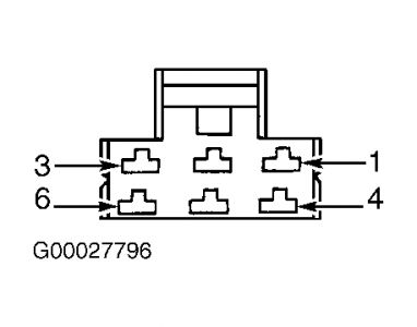
DRIVER DOOR LOCK SWITCH Remove DDM. See DOOR LOCK SWITCH under REMOVAL & INSTALLATION. Measure resistance between DDM C1 connector terminals No. 7 and 11 (component side) while operating driver door lock switch in specified positions. See Fig. 37 . Compare readings with specifications. See DRIVER DOOR LOCK SWITCH POSITION RESISTANCE table. If resistance is not as specified, replace DDM. NOTE: Driver door lock switch is integral with the Driver Door Module (DDM).


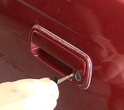
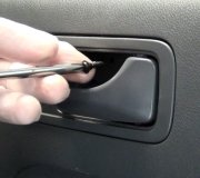
First pic is drivers switch, other is passenger.

Friday, August 21st, 2009 AT 1:32 PM


