Hello -
Thanks for the info. . .. . ..
Let's start with the fuel pump. . .. . .. . .. . ..I have the test below. . .. . .try to retrace putting the fuel pump in. . .. . ..the sending unit is attached, the float etc. . .. . ..it may be in a bind. . .are you sure all electrical connection were connected?
Do the test and see what you find there. . .. . .. . .. . ..
FUEL GAUGE & FUEL TANK SENDING UNIT TEST
NOTE: DO NOT leave sending unit lead grounded for extended periods; gauge damage will result.
Dakota
1. Test fuel gauge and wiring by grounding fuel tank sending unit lead. Turn ignition on, and note gauge reading. DO NOT leave sending unit lead grounded for extended periods; gauge damage will result.
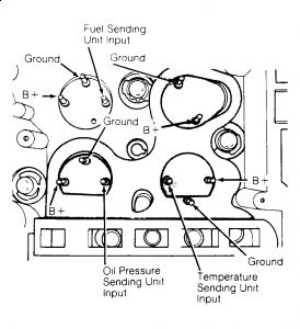
2. If gauge indicates maximum reading, wiring and fuel gauge are operating properly. Go to step 4). If gauge does not indicate maximum reading, remove gauge. Using a voltmeter, check for battery voltage between B+ pin and ground pin. See Fig. 1.

Fig. 1: Identifying Instrument Panel Gauge Pins (Dakota)
Courtesy of CHRYSLER MOTORS.
3. If voltage reading is not as specified, check wiring connections and instrument panel printed circuit board continuity. If wiring and circuit board test okay, replace fuel gauge.
4. If gauge indicates maximum reading in step 2), remove fuel tank sending unit. Connect a jumper wire between sending unit body and chassis ground. Install sending unit harness connector. Move float arm to FULL, then EMPTY position. Note fuel gauge readings at each float arm position. Allow at least 2 minutes at each test point for gauge to stabilize.
5. If no reading or improper reading is obtained at either test position, replace sending unit. If sending unit tests okay, check for damaged ground wire or poor connection. Ensure float assembly does not bind in fuel tank and tank is not damaged. Repair as required.
Was the fuel and tach working prior to the tanny R&R?
Code 15 is NO VEHICLE SPEED SIGNAL No Distance Sensor Signal Detected During Road Load Conditions. That is located on side of the transmission. . ...check the connections. . .the sensor may be defective.

The Tach. . ...the computer controls this. . .check Fuse 6, 15 amp with an ohm meter and see what you have.
6 - 15 Amp (Lt. Blue)
Horn, Tachometer.
TACHOMETER (DAKOTA)
SBEC provides signal to drive tachometer on Dakota. SBEC Single Board Engine Controller
Unless you have the proper equipment you may not be able to check that. Check the suggestions below.
SINGLE BOARD ENGINE CONTROLLER (SBEC)
Harness Check
1. If SBEC is found to be faulty during SELF-DIAGNOSTICS testing, perform following steps to confirm diagnosis. Most components are incorrectly diagnosed due to faulty electrical connectors or poor connections between component and vehicle. Sometimes, simply disconnecting and connecting an electrical component will provide a good electrical connection.
2. Before replacing an SBEC, check all components in suspected circuit. If components are okay, carefully disconnect SBEC from vehicle harness.
3. Inspect SBEC harness connector and SBEC contact pins for corrosion, bent pins, missing pins, spread cavities and broken wires. Clean, repair or replace connector as necessary.
4. Connect SBEC harness connector to SBEC, and retest system using Diagnostic Readout Box (DRB-II) or similar scan tool. See appropriate G - TESTS W/ CODES article in the ENGINE PERFORMANCE Section. If vehicle does not pass test and fails with same message, replace SBEC.
I apologize I don't have a test for the sensor other than with equipment. . .. . ...
You are correct. . ..55 is that is the end. . .. . .. . .. . ..12???? don't have that one. . ...could that be a miss count??
SPONSORED LINKS
Tuesday, September 22nd, 2009 AT 8:08 PM


