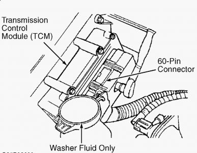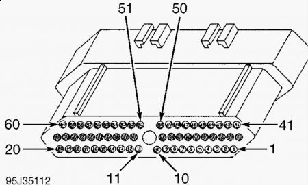
TEST TC-96A - NO CCD MESSAGES FROM TRANSMISSION CONTROL MODULE (TCM) 1. Connect scan tool to data link connector. Turn ignition on. Select TRANSMISSION and then 41TE on scan tool. Scan tool automatically performs a self-test on the CCD bus. If scan tool displays BUS OPERATIONAL, go to next step. If scan tool displays does not display BUS OPERATIONAL and a CCD bus failure message such as SHORT TO BATTERY or SHORT TO GROUND is displayed, see VEHICLE COMMUNICATIONS section of BODY CONTROL COMPUTER article in ACCESSORIES & EQUIPMENT section. 2. Select ENGINE MODULE on scan tool. Using scan tool, clear Diagnostic Trouble Codes (DTCs) from Powertrain Control Module (PCM). Raise and support vehicle so all wheels are off the ground. 3. Start engine and allow engine to idle. Place shift lever in Drive, allowing front wheels to rotate for one minute. Apply brakes. Place shift lever in Park. Using scan tool, check for stored DTCs. 4. If scan tool displays NO CCD MESSAGE FROM TCM, go to step 8 . If scan tool does not display NO CCD MESSAGE FROM TCM, go to next step. 5. Conditions required to set DTC are not present at this time. The PCM and TCM communicate messages across the CCD bus, as information from either module is needed to operate their respective systems. DTC may be stored in PCM when no CCD bus messages are received from TCM for 10 seconds. Possible causes are: open circuit in CCD bus, TCM is not powered up, defective TCM or defective PCM. 6. Check for defective wiring or connections at PCM and TCM. The PCM is located between driver's side front fender and power distribution center, near battery. The TCM is located on passenger's side front corner of engine compartment, on inner fender, near windshield washer reservoir. See Fig. 65 . Fig. 65: Locating Typical Transmission Control Module (TCM) 7. If wiring or connectors are damaged, repair as necessary. Perform TEST VER-2A - ROAD TEST VERIFICATION . If wiring and connectors are not damaged, see INACTIVE TROUBLE CODE CONDITION . Perform TEST VER-2A - ROAD TEST VERIFICATION . 8. Ensure ignition is off. Disconnect connectors at PCM and TCM. The PCM is located between driver's side front fender and power distribution center, near battery. The TCM is located on passenger's side front corner of engine compartment, on inner fender, near windshield washer reservoir. See Fig. 65 . 9. Using ohmmeter, check resistance between PCM connector terminal No. 59 (Violet/Brown wire) and TCM connector terminal No. 43 (Violet/Brown wire). If resistance is less than 5 ohms, go to next step. If resistance is 5 ohms or more, repair open circuit in Violet/Brown wire between PCM and TCM. Perform TEST VER-2A - ROAD TEST VERIFICATION . 10. Using ohmmeter, check resistance between PCM connector terminal No. 60 (White/Black wire) and TCM connector terminal No. 4 (White/Black wire). If resistance is less than 5 ohms, go to next step. If resistance is 5 ohms or more, repair open circuit in White/Black wire NOTE: For connector terminal identification, see CONNECTOR IDENTIFICATION . For wiring diagram, see WIRING DIAGRAMS article.between PCM and TCM. Perform TEST VER-2A - ROAD TEST VERIFICATION . 11. Reinstall connectors on PCM and TCM. Turn ignition on. Select TRANSMISSION and then 41TE on scan tool. If scan tool displays NO RESPONSE, replace TCM. Perform TEST VER- 2A - ROAD TEST VERIFICATION . If scan tool does not display NO RESPONSE, replace PCM. Perform TEST VER-2A - ROAD TEST VERIFICATION .
1/16/2010 ...


I will email a PDF on the PCM connector, as it is more detailed...this is the TCM connector.
SPONSORED LINKS
Saturday, January 16th, 2010 AT 11:21 AM


