Crankshaft Position Sensor intermittent P0385 code?

1996 FORD BRONCO
280,000 MILES • 5.8L • 4WD • AUTOMATIC
Avatar
JOSH_019
  • MEMBER
  • 19 POSTS
I have a 1996 Ford Bronco with the 5.8L that has an intermittent P0385 code. It generally runs and drives normally with no noticeable misfire or drivability problem.(FORScan shows no misfires during any of this)

The problem is very intermittent. At one point it went about a year without setting the code, then started happening every few weeks, and lately it has become somewhat more frequent but is still unpredictable.

What I’ve done/tested:

* Replaced the MD/MFDS (misfire detection) sensor more than once.
* Replaced the sensor pigtail/harness and have also checked the wiring for continuity.
* Previously ran/considered dedicated jumper wires to eliminate the factory harness as a possible source of interference/grounding issues.
* Checked the sensor resistance and found it within specification.
* Measured approximately 0.5V AC from the sensor while the engine is running.
* Had the harmonic balancer rebuilt/replaced, with no change to the problem.
* Removed and inspected the PCM. There is no obvious physical damage or damaged circuits.
* Had an electronics repair shop inspect the PCM. They reportedly checked the circuit, solder joints, capacitors, diodes and fuses. They traced the MD circuit to an IC/chip but said the circuit components themselves tested normally.
* KOER self-test does not reproduce the P0385.
* The code occurs during normal driving rather than immediately during KOER.
* With FORScan, the code will initially show as pending/“expected to be confirmed,” then later become confirmed after additional driving.
* When the code is not present, the engine appears to run normally and the OBD data looks generally healthy.

Unfortunately this has been an ongoing problem for years and it seems like every year or so the code comes on and I go down this rabbit hole. I’d like to fix it once and for all. Thank you!
Aug 15, 2026 at 7:29 PM
Advertisement
Avatar
AL514
  • Experienced Mechanic
  • 5,639 POSTS
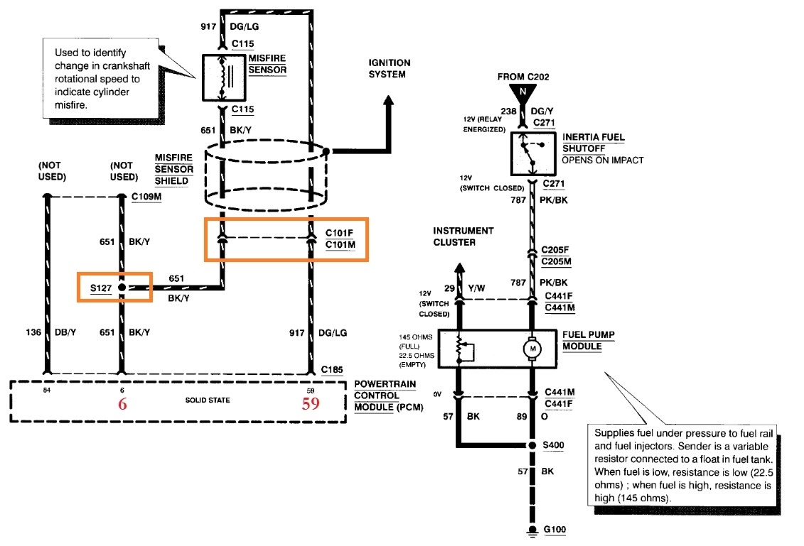
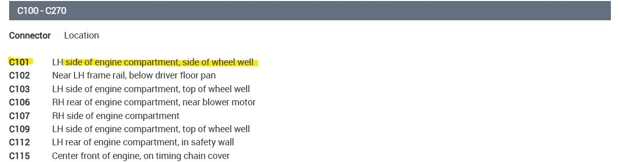
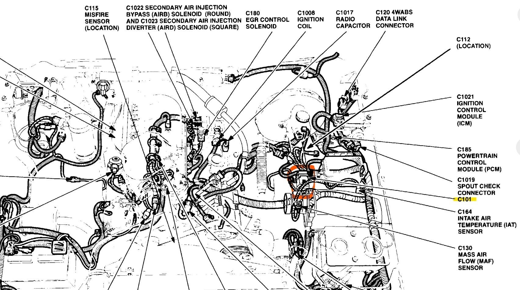
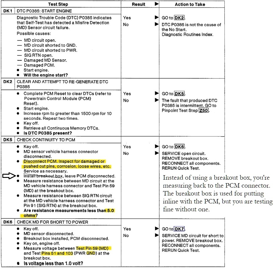
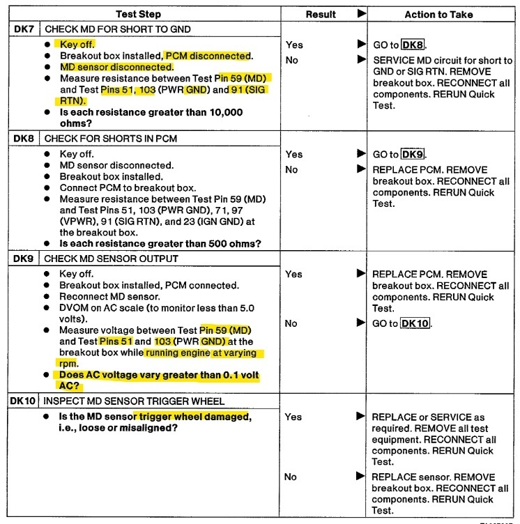
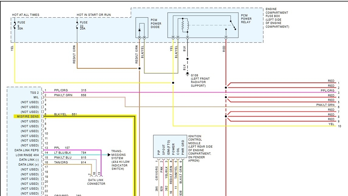
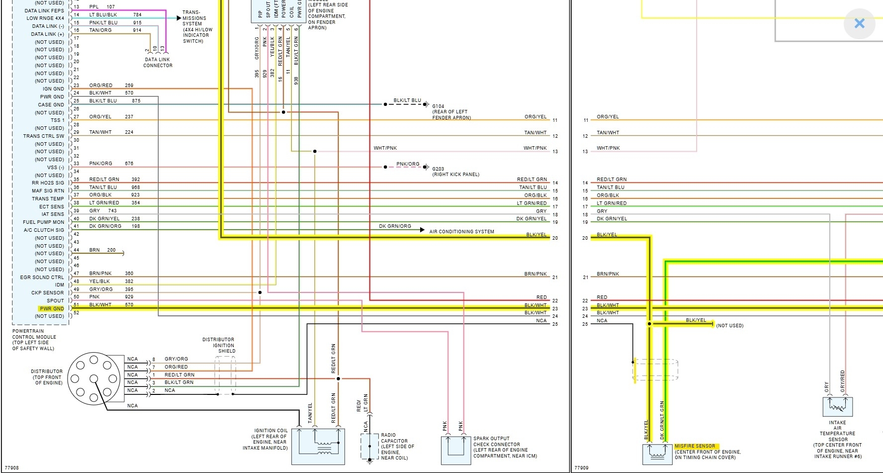
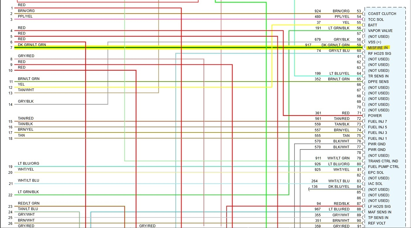
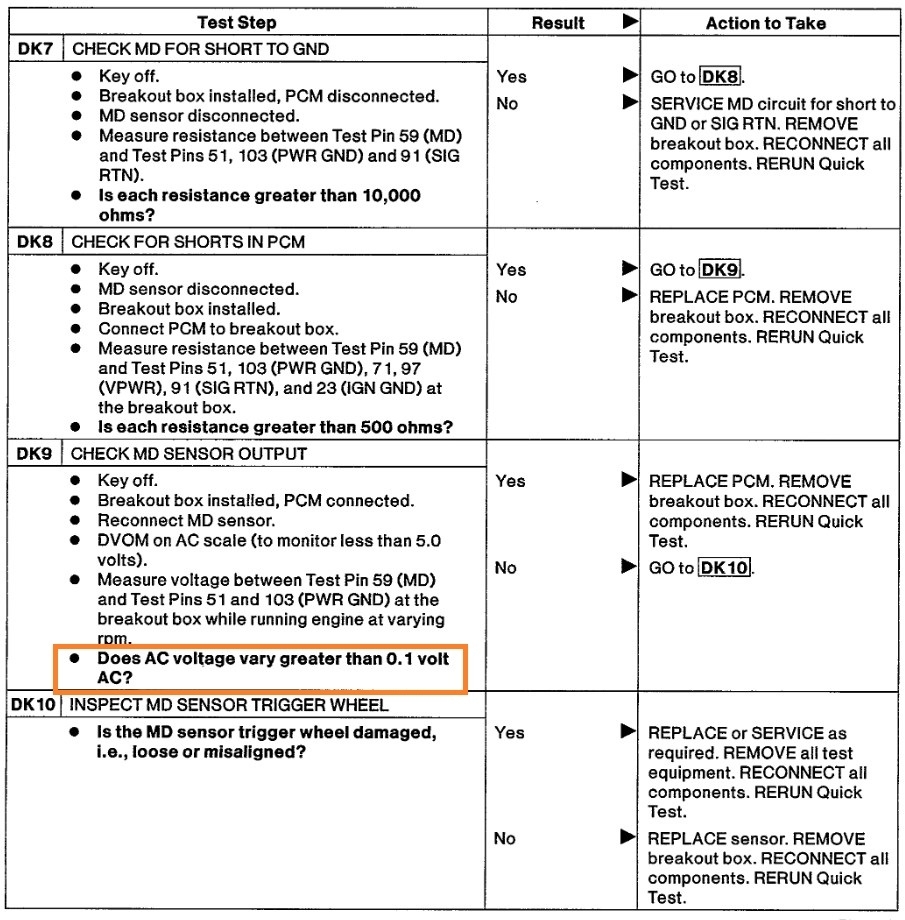
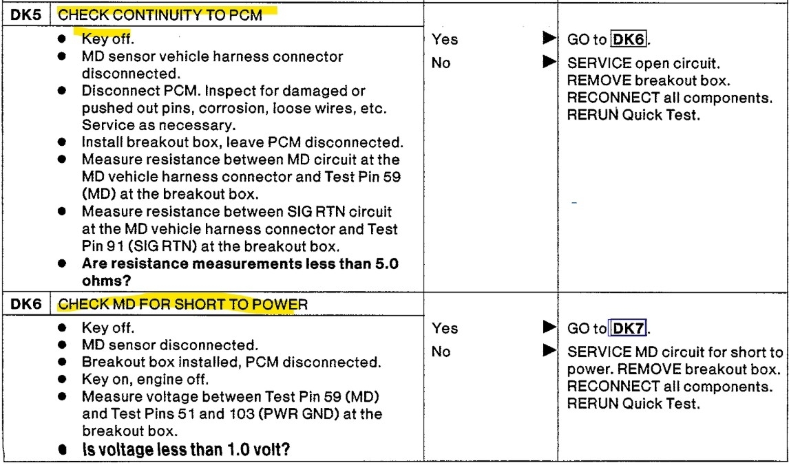
Hello, intermittents like this once a year thing are the worst. Im not sure if you notice it more during summer or winter. Heat and cold do all kinds of things to circuit boards and sensors. But there is a flow chart for this code ill post for you to follow. I also see a connector C101 inline with the Misfire sensor, so thats something to check for corrosion. Service info has it located LH side (drivers) of engine compartment, side of wheel well. Ill post a diagram showing its location. Along with corrosion, check for loose pins inside the connectors as well.

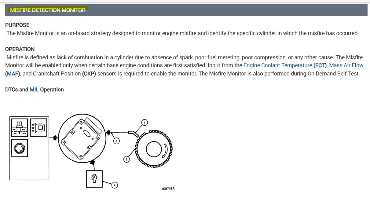
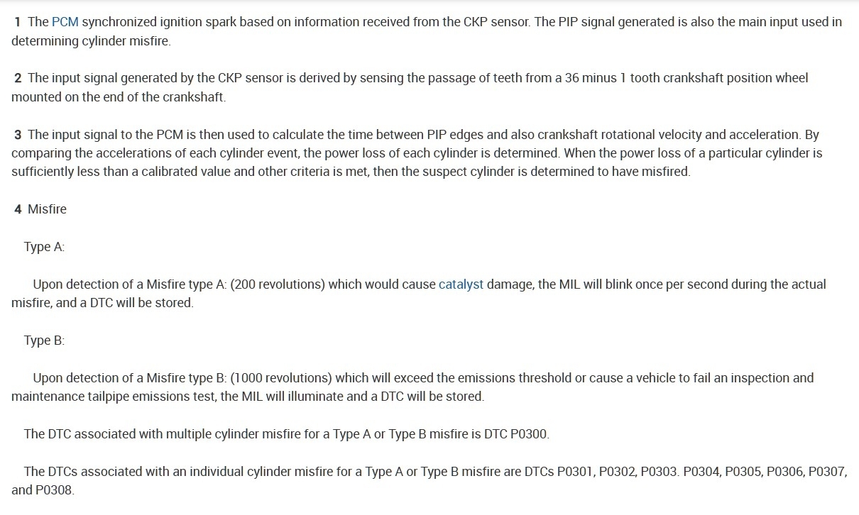
Service info also states the misfire sensor monitors the crankshaft speed, so basically its an inductive crank sensor. It has a shield over the wire which is to protect from ignition interference. You will see on the oem wiring diagrams there is also a splice S127, not used, but can still cause issues.

You mentioned checking the resistance of the wiring from the PCM to the misfire sensor, are you getting less than 5 ohms of resistance from one end of a wire to the other with both the PCM and misfire sensor unplugged? Resistance tests will really only tell you if the circuit it actually complete. But its what the flow chart has you do. I will post all this info for you, and you can look through it.

If you're getting a strange resistance reading on either of the sensor's wires we can load test the wires each and make sure they can carry current. Let me get the rest of this is info ready for you.
Aug 16, 2026 at 12:30 PM
Avatar
AL514
  • Experienced Mechanic
  • 5,639 POSTS
Here is the service info for that code and the wiring diagrams, I know you have tested all this already I am sure, but hopefully this will help knock this issue for once. I would go right to that C101 connector first and check it, its a bulk connector not bad to get to. With the shielding on that wire that is supposed to help with interference on the misfire sensor's wiring, so check that as well. This is where a scope would come in. I have had poorly routed wiring harnesses, running right by ignition coils, give voltage spikes on the grounds too and I can see a strike from a coil causing that sensor to read a misfire because the sensor's signal is going to drop right out for that split millisecond looking exactly like the crankshaft slowing down, which is what a cylinder misfire does.
Also notice the AC voltage reading. But before ever replacing a PCM, always try to exhaust all other possiblities, no pun intended. Look for corrosion first. And it will be tough to catch this fault without a scope, or to at least see it happening, but you can still find the issue. I look for corrosion everywhere when doing visual inspection on any diag just because its such a common fault. Let us know what you find, I am curious.
Aug 16, 2026 at 1:05 PM
Avatar
JOSH_019
  • MEMBER
  • 19 POSTS
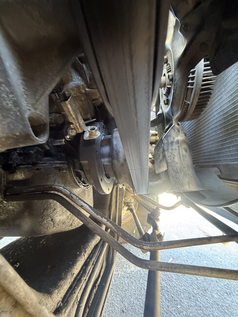
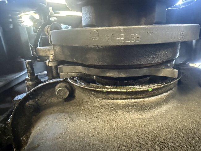
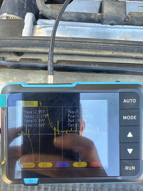
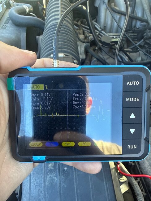
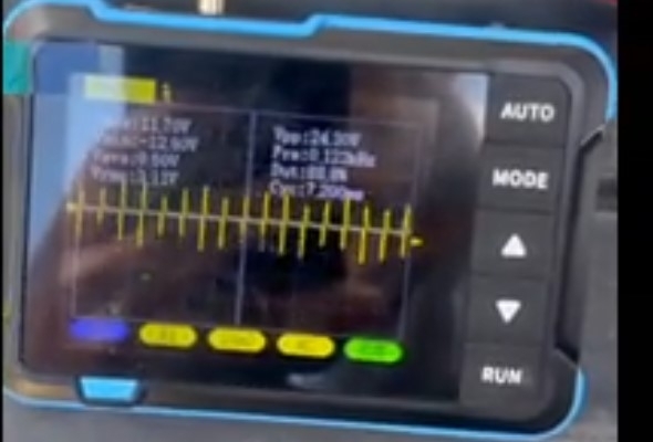
Hi I’m not that savvy on the oscilloscope readings but I’ll attach the screenshots from readings at pin 59 and directly at the sensor at idle. I’ll also attach pics of harmonic balancer and reluctor rings to see if there’s anything you see. But all of the wiring and checking for shorts per the DK steps were normal.
Aug 31, 2026 at 3:17 PM
Avatar
STRAILER
  • Experienced Mechanic
  • 55,214 POSTS
You have already covered most of the common causes of this code, and based on your testing I would stop replacing the MD/MFDS sensor. The fact that the engine runs normally, FORScan isn't showing misfires, and the code can take quite a while to return points more toward an intermittent signal problem than a mechanical misfire. Can I ask if this is the original engine with timing chain? The reason I ask is if the timing chain is bouncing around with excessive play you will get this code no matter what you do until the chain is replaced FYI.
Sep 1, 2026 at 4:43 PM
Avatar
JOSH_019
  • MEMBER
  • 19 POSTS
Yes it is an original motor and timing chain. And ya the FORScan doesn’t show any misfires. And it passes the KOER self check which when the sensor was bad it was failing that. But when driving it almost immediately goes to a pending code for the crankshaft sensor then eventually throws the actual code
Sep 1, 2026 at 4:53 PM
Avatar
AL514
  • Experienced Mechanic
  • 5,639 POSTS
Hello, I would suggest what Ken mentioned about replacing the sensor, they cant cost too much. It might be that the sensor is borderline when it comes to the KOER test. Looking at the 2 scope captures, I see youre on a 200mv/div on both captures but obviously there is a difference in the 2 signals, if I am seeing the scope screen correctly. This being a 2 wire sensor, its a inductive type pick up, so you would expect to see a nice sinewave signal. The 2nd capture has a bit of a sinewave, but its not going low and the first capture looks to have exceeded your settings. You dont want to see two different signals coming from a crank sensor like that. Unless Im missing something in that first larger capture.
I would unplug the sensor and PCM connector, load test each wire independently with a turn signal bulb, so you know the circuit can carry current. Also with each circuit isolated, check each wire for continuity to ground just to be sure theres no shorts to ground. You should have no path to anything with both ends unplugged. Once you have checked the wiring with a load test, that leaves you with the sensor, PCM, or reluctor wheel. Go grab a used one from a used auto parts yard and throw it in, quick test for cheap. But let us know what you find.
Sep 1, 2026 at 8:21 PM
Avatar
JOSH_019
  • MEMBER
  • 19 POSTS
Ok thank you. I have tested all of the wires and the pcm’s for shorts and grounds. The sensor has been replaced but then again this will be the 4th sensor I’m replacing. In the past the KOER test would fail with the P0385 on the test.

Is it possible that the sensor just isn’t hitting the reluctor wheel straight on? The reluctor wheel and harmonic balancer just got all replaced and the PCM was tested at an electronics shop and all circuits were working fine. I seem to think it’s something at the sensor or interference.

My goal with the scope was to see if I’m getting the right wave form at the pcm and at the sensor. Are you able to expand on what you’re interpreting with my scope readings? Thanks!!
Sep 1, 2026 at 10:25 PM
Avatar
AL514
  • Experienced Mechanic
  • 5,639 POSTS
One thing I notice, on your 2nd scope capture, that huge spike that happens before you see the weak crank signal. At least in that capture, the PCM has a certain threshold or voltage level it will consider a signal. And that spike is at least half of the crank signal that comes next. That is enough to trick a computer into seeing a signal. The 1st capture looks like a mess. I would try to get a bit more zoomed out picture so we can see how often those voltage spikes are occuring. They will most likely be ignition or injector spikes. I have seen these on ground side where the manufacturer had run the harness, including the main PCM grounds right next to 3 coils, and there were spikes everywhere. One 02 sensor I had to re-route the sensors wiring away from coils and the signal cleaned up nicely. That sensor is there to read and variation in crank shaft speed, so spikes in the signal happening earlier or later than the intended signal, the PCM will take that as the crank slowing or speeding up, indicating a misfire. But instead of a misfire code we get a malfunction code because the spikes are just all over the place. Even though the PCM is designed to deal with some interference, that much might be too much. You could temporarily run wires and see if it makes a difference. That would rule out the interference part. You dont have to cut everything out to overlay some wires for testing.
Sep 1, 2026 at 11:41 PM
Avatar
JOSH_019
  • MEMBER
  • 19 POSTS
Here is better quality scope at crankshaft sensor and also one at pin 59. Still throwing the code. During the drive it didn’t have any misfires but still throws the code under some load seems like.

As for the timing chain I disconnected the spout connector and the 10BTDC under load and at idle only moved appx 2 degrees and at idle is perfectly still so doesn’t seem like there’s a lot of slack in the chain.
Sep 4, 2026 at 9:00 PM
Avatar
AL514
  • Experienced Mechanic
  • 5,639 POSTS
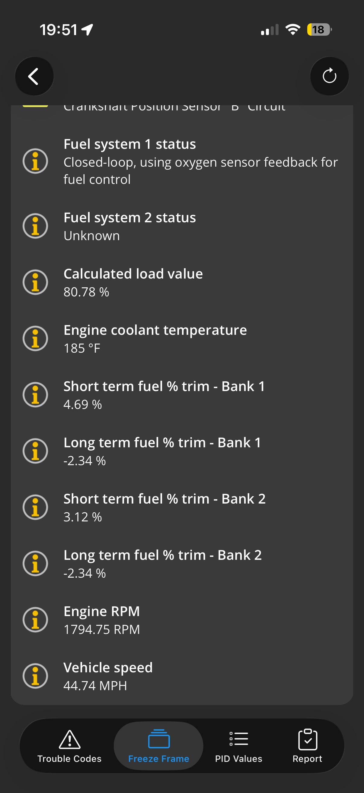
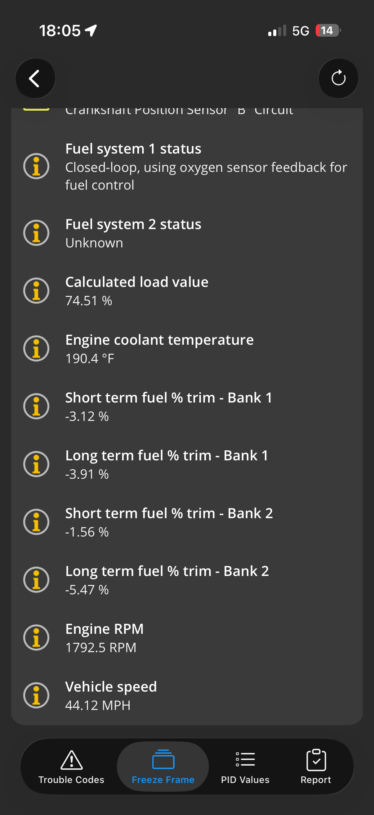
well your fuel trims look beautiful in that scan data, I cant tell what your scope settings are, I am going to try to get a better zoomed in view of them.
Sep 4, 2026 at 9:22 PM
Avatar
AL514
  • Experienced Mechanic
  • 5,639 POSTS
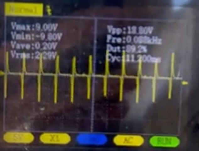
Ok looking at your scope data (which I hope I am seeing correctly), the Vmax, that voltage being at 10.3volts on a 2 wire variable reluctance sensor is incorrect. It should not be producing such a high voltage like that. Either the sensor is too close to the reluator pick up, or the sensor is failing (the resistance spec unplugged looks to be 300-500 Ohms range).
Another check you can do it just scope the sensor itself unplugged. Its a variable reluctance sensor so it makes it's own voltage. Unplug it, and hook up your scope to just the sensor and see if that 10volts disappears, thats what it setting your code. Thats way over the voltagae threshold for that sensor. And the PCM is not happy about it,.
Sep 4, 2026 at 9:38 PM
Avatar
JOSH_019
  • MEMBER
  • 19 POSTS
Ok I’ll try that. Just to clarify that higher voltage was only at higher rpm. At idle it stayed around 5v
Sep 4, 2026 at 10:01 PM
Avatar
AL514
  • Experienced Mechanic
  • 5,639 POSTS
Yes, even 5v at idle in incorrect. the reason it produces a higher voltage at higher rpms is simply because its spinning faster creating a stronger magnetic field, but that high of a voltage is passed the threshold. Id would be curious to see the scope waveform of just the sensor. I was thinking maybe there was a short to power, but then you would have higher voltage all the time. This type crank sensors make a sinewave going positive and negative a small amount, (not a Squarewave signal), the amplitude increases as speed increases. But this is only a misfire sensor and only has 4 tabs that pass the sensor. So its a slower signal than a crank sensor signal. But sensor distance to trigger wheel is very important, it might be too close to the tabs. Maybe try moving it away if its adjustable.
Its not a Hall Effect sensor with 3 wires that is fed a 5volt reference. Thats is the other type. Although this one is supposed to have a shield wire around the two sensor wires if service info is correct.
Sep 4, 2026 at 10:45 PM
Avatar
JOSH_019
  • MEMBER
  • 19 POSTS
Ok the resistance was within normal limits but I bought a new sensor just in case. I’m getting the same readings for voltage. I hooked up the scope to the sensor only and it’s the exact same readings as I was getting from the PCM when I back probed it. I hooked up the scope and went for a drive and I’m able to figure it’s throwing the “impending code” at appx 40-45mph and 1700rpm everytime. But on the scope I’m not having any dropout or anything. I also ran new wires to bypass the original harness and nothing changed I’m getting the exact same result. I also replaced the connector just to be sure also no difference. I checked the harmonic balanced and reluctor rings and they’re all in good shape and not wobbling or loose. The gap between the reluctor wheel and the sensor is appx .035.

I’ll attach a video of the wave form and you can see that when driving I’m not dropping any waves
Sep 7, 2026 at 7:11 PM
Avatar
AL514
  • Experienced Mechanic
  • 5,639 POSTS
well you have most certaintly covered almost everything. I assume on your above live data, at the top there, thats something to do with the crank sensor circuit B? And are you going up hill or under heavy throttle? That Calculated Load value looks high. But I will look more into this code criteria right now to see if theres something specific, because the waveform does look ok.
With just the key On, engine off, unplug the sensor and see what you get for a reading on each wire itself to ground. Lets see if theres a bias voltage coming from the PCM, or if its missing. Also, with the key Off, check each wire for a short to ground, I know you have probably already done this, I can see you know what you are doing. But lets make sure none of those wires are shorted to anything.
Im wondering if the high voltage is coming from the PCM itself. I will look more into the code as well though.
Sep 7, 2026 at 9:52 PM
Avatar
AL514
  • Experienced Mechanic
  • 5,639 POSTS
This scope captures tell alot. I grabbed from your a couple video clips with the vehicle at higher rpm. This looks like the trigger wheel or harmonic balancer broke free from the inner section causing the balancer to gap too vary, in turn causing the sensor signal to do the same. the service info posted earlier with the meter on 5VAC, "Does the AC voltage vary greater than 0.1v AC? I wonder about the key for the balancer as well.
Zoom in on that waveform to get a better look at each pulse too.
Sep 7, 2026 at 10:34 PM
Avatar
AL514
  • Experienced Mechanic
  • 5,639 POSTS
that upper pulse is almost a full volt under the negative pulse. I wouldnt go replacing the PCM until we have exhausted the possiblity of the trigger wheel not being straight.
That is a variation of more than 0.1volts.
Sep 7, 2026 at 10:37 PM
Join 2CarPros for free, one of the most advanced car repair communities on the internet. From first-time drivers to seasoned mechanics, everyone is welcome to reply, share details, and get better answers. You can add a temporary image or video first; uploads are limited to 20 MB.
Ask a Free Question
Repair Safety Notice: This information is for general instructional purposes only. Vehicle repair can be dangerous. Verify all information, follow manufacturer service procedures, use proper tools and safety equipment, and consult a qualified repair shop when needed.