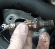
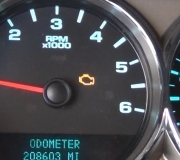
You assumed incorrectly. It is possible for the O2 sensor circuit malfunction, but that does not necessarily mean the O2 sensor being bad.
DTC P0171: 1/1 FUEL SYSTEM LEAN (Bank 1)
Monitored & Set Conditions
Fuel system lean condition is monitored when engine is running in closed loop, ambient temperature is more than 20°F (-7°C), battery temperature is more than 20°F (-7°C) and altitude is less than 8000 feet. DTC will be stored in Powertrain Control Module (PCM) memory if PCM multiplies short term compensation by long term adaptive and a certain percentage is exceeded for 2 trips. ***Usually when the vehicle is cold***
Possible causes for DTC to set are: intermittent condition, defective fuel pump module, defective Throttle Position (TP) sensor, restricted fuel inlet strainer on fuel pump, defective Engine Coolant Temperature (ECT) sensor, defective Manifold Absolute Pressure (MAP) sensor, engine mechanical problem, defective Heated Oxygen Sensor (HO2S), defective fuel filter, defective fuel pressure regulator or PCM.
Testing
1. Turn ignition on. Using scan tool, read DTCs. If Good Trip counter for DTC P0171 is displayed and displayed count is "0", go to next step. If Good Trip counter for DTC P0171 is not displayed or displayed count is not "0", go to step 16.
2. Turn ignition off. Release fuel pressure. See FUEL SYSTEM PRESSURE RELEASE. Remove test port cap from fuel rail. Install a fuel pressure gauge to test port on fuel rail. Turn ignition on. Using scan tool, actuate ASD fuel system test. Allow fuel pressure gauge to stabilize. Stop ASD fuel system activation. Fuel pressure should be 53-63 psi (3.73-4.43 kg/cm2). If fuel pressure is as specified, go to next step. If fuel pressure is less than specified, go to step 13. If fuel pressure is more than specified, replace pressure regulator. See FUEL SYSTEMS in appropriate REMOVAL, OVERHAUL & INSTALLATION article.
3. Turn ignition on. Using scan tool, read 1/1 HO2S voltage. If voltage is.4-.6 volt, go to next step.
If voltage is not.4-.6 volt, go to step 10.
4. Turn ignition off. Wait at least 10 minutes to allow HO2S to cool. Turn ignition on. Using scan tool in SENSOR mode, monitor 1/1 HO2S voltage until voltage stabilizes at.4-.6 volt. Using scan tool, actuate HO2S HEATER TEST and monitor 1/1 HO2S voltage for 2 minutes. If voltage does not stay at.4-.6 volt, go to next step. If voltage stays at.4-.6 volt, replace 1/1 HO2S.
5. Ensure ignition is on. Ensure throttle plate is fully closed against stop. Using scan tool, read TP sensor voltage. If voltage is less than.92 volt, go to next step. If voltage is.92 volt or more, check throttle plate and linkage for binding. Repair throttle plate and linkage as necessary. If throttle plate and linkage are okay, replace TP sensor.
6. Ensure ignition is on. Using scan tool, read TP sensor voltage. Slowly open and close throttle
plate while monitoring TP sensor voltage. If voltage change is smooth, go to next step. If voltage change is erratic, replace TP sensor.
7. Turn ignition off. Connect a vacuum gauge to manifold vacuum source. Start engine and allow it
to idle. If engine will not idle, maintain a constant RPM. Using scan tool in SENSOR mode, monitor Manifold Absolute Pressure (MAP) vacuum value. Compare scan tool reading with vacuum gauge reading. If scan tool reading is within one in. Hg of vacuum gauge, turn ignition off and go to next step. If scan tool reading is not within one in. Hg of vacuum gauge reading, replace MAP sensor.
8. Turn ignition on. Using scan tool, read ECT sensor value. If engine coolant temperature is more than 180°F (82°C), allow engine coolant temperature to cool down to 150°F (66°C) before proceeding. If engine coolant temperature is 150°F (66°C) or less, start engine and monitor scan tool until engine coolant temperature reaches 180°F (82°C). If ECT sensor value increases smoothly and reaches at least 180°F (82°C), go to next step. If ECT sensor value increase is erratic or does not reach at least 180°F (82°C), check for cooling system problems. Repair cooling system as necessary. If cooling system is okay, replace ECT sensor.
9. Check the following additional items as possible mechanical problems:
Engine vacuum must be at least 13 in. Hg with shift selector in Neutral.
Engine valve timing must be within specification.
Engine compression must be within specification.
Engine exhaust system must be free of restrictions.
Engine Positive Crankcase Ventilation (PCV) system must flow freely.
Torque converter stall speed must be within specification.
Power brake booster must have no internal leaks.
Fuel must be free of contamination.
Fuel injectors must be free of restrictions.
Fuel injector control wires must be installed on correct injector.
Repair any mechanical problems as necessary. If no mechanical problems exist, test is complete.
10. Ensure ignition is on. Disconnect 1/1 HO2S connector. Using scan tool, read 1/1 HO2S voltage. If
voltage is not.4-.6 volt, go to next step. If voltage is.4-.6 volt, replace 1/1 HO2S.
11. Turn ignition off. Disconnect PCM connectors. PCM is located on left side of engine compartment, near front of battery. Measure resistance between ground and Dark Blue/Light Blue wire at 1/1 HO2S harness connector. If resistance is 5 ohms or more, go to next step. If resistance is less than 5 ohms, repair short to ground in Dark Blue/Light Blue wire between PCM and 1/1 HO2S.
12. At this time, PCM is assumed to be defective. Replace PCM. Program the new PCM.
SPONSORED LINKS
Tuesday, February 24th, 2009 AT 1:30 PM


