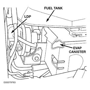
DTC P1495: LEAK DETECTION PUMP SOLENOID CIRCUIT
Monitored & Set Conditions
Circuit is monitored immediately after a cold start, with battery/ambient temperature 40-90°F (4-32°C)
and engine coolant temperature within 10°F of battery/ambient temperature. DTC will set if PCM senses state of solenoid circuit does not match PCM's desired state.
Possible Causes
Wiring Harness Intermittent
Leak Detection Pump
Fused Ignition Switch Output
LDP Solenoid Control Circuit Shorted To Ground
LDP Solenoid Control Circuit Open
PCM
Testing
1. Turn the ignition on. With the DRBIII(R), read DTCs. Is the Good Trip counter displayed and equal to zero? If yes, go to next step. If no, go to step 7 .
2. Turn the ignition off. Disconnect the Leak Detection Pump harness connector. Using a 12-volt test light, connect one end to the Fused Ignition Switch Output circuit and the other end to the LDP
Solenoid Control circuit at the Leak Detection Pump harness connector. Turn the ignition on. With the DRBIII(R), actuate the Leak Detection Pump. Does the test light flash on and off? If yes, replace the Leak Detection Pump. If no, go to next step.
3. Using a 12-volt test light connected to ground, probe the Ignition Switch Output circuit in the Leak Detection Pump harness connector. Does the test light illuminate brightly? If yes, go to next step. If no, repair the Fused Ignition Switch Output circuit.
4. Turn ignition off. Disconnect PCM C2 harness connector. Measure the resistance of the LDP
Solenoid Control circuit in the Leak Detection Pump harness connector to ground. Is the resistance below 5.0 ohms? If yes, repair the LDP Solenoid Control circuit for a short to ground. If no, go to next step.
5. Measure the resistance of LDP Solenoid Control circuit between Leak Detection Pump harness
connector and the PCM C2 harness connector. Is the resistance below 5.0 ohms? If yes, go to next step. If no, repair the LDP Solenoid Control circuit for an open.
6. There are no possible causes remaining, replace PCM. Program the new PCM.
7. At this time, the conditions required to set the DTC are not present. Use the Freeze Frame Data to
help you duplicate the conditions that set the DTC. Pay particular attention to the DTC set conditions, such as, VSS, MAP, ECT, and Load. Visually inspect the related wire harness. Look for any chafed, pierced, pinched, or partially broken wires. Visually inspect the related wire harness connectors. Look for broken, bent, pushed out, or corroded terminals. Refer to any Technical Service Bulletins (TSB) that may apply. Perform a wiggle test of the LDP wiring while the circuit is actuated with the DRBIII(R). Listen for the LDP to quit actuating. Also watch for the Good Trip counter to change to zero. Were any problems found? If yes, repair wiring harness/connectors as necessary. If no, test is complete.
***Didn't you say you heard "hissing" by the tail pipe. Your EVAP charcoal canister is next to your fuel tank. I would say that is a close vicinity to your tail pipe. Could it be possible that the vacuum line to the canister had broken off (or simply came off) and that is the "hissing" that you heard? If you have an EVAP leak, you will jerk and sputter as if the car not getting enough gas.***

Let me know...
Sunday, January 18th, 2009 AT 11:00 PM


