C, K, R & V MODELS
Disconnect battery ground cable.
Disconnect electrical connector at switch.
Remove switch mounting screws, then the switch.
Position shift lever in neutral gate notch.
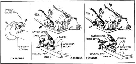
Insert a .098 inch gauge pin into switch gauge hole as shown, Fig. 13, then assemble switch to column by inserting carrier tang into shift tube slot.
Install switch mounting screws into retainers. If retainers strip, they must be replaced.
Remove gauge pin, then position shift lever into Park to shear internal plastic pin in switch.
Return shift lever to neutral gate notch, then ensure switch gauge hole will accept .080 inch gauge pin. If not, loosen mounting screws, then rotate switch on column until .098 inch gauge pin can be reinserted into gauge hole.
Reconnect electrical connector and battery ground cable.
Fig. 13 Neutral start switch replacement. Series 10---30/1500---3500
G & P MODELS
Raise and support vehicle, then disconnect battery ground cable.
Disconnect electrical harness from switch.
Remove switch to mounting bracket retaining bolts and the switch, Fig. 13.
Loosely install new switch to mounting bracket, then align .093---.097 inch hole in transmission lever with hole in switch assembly. Insert pin to hold in neutral position, Fig. 13.
Set transmission lever in neutral position by moving lever counterclockwise to L1 detent, then move clockwise three detents.
Install rod into transmission and switch levers and secure with clips.
Tighten switch retaining bolts, lower vehicle and check switch for proper operation.
Wednesday, October 27th, 2010 AT 10:17 PM


