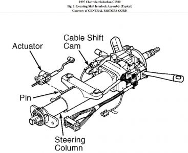
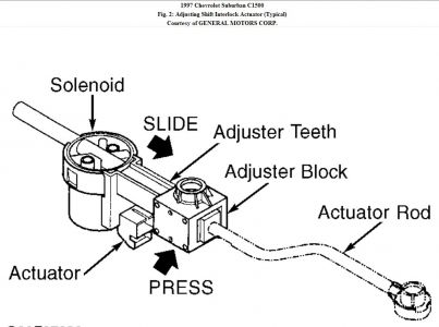
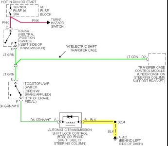
Visual inspection diagnosis of shift interlock system should begin with a general visual inspection. Before beginning any diagnosis, refer to wiring diagram to become familiar with the type of system being diagnosed and for use as a guide to pinpoint areas of concern. See wiring diagrams . Once familiar with system being diagnosed, check operation of the following: with ignition switch in lock position, gearshift lever should be locked in park. with gearshift lever in park, ignition switch should be allowed movement from lock position to any desired position and back to lock position. Ignition key should be removable while in lock position. with ignition switch in run position, gearshift lever should be allowed movement from park. Models equipped with shift interlock solenoid require that brake pedal be depressed for this operation. with ignition switch in run position and gearshift lever in any position other than park, ignition key is non-removable. Ignition key is removable only when gearshift lever is returned to park. If shift interlock system operates as specified, system is functioning properly at this time. If system does not operate as specified, inspect mechanical functions of the following: ignition switch. gearshift lever assembly. external shift cable/linkage. internal trans-axle/transmission shift linkage. Adjust or repair as necessary. See adjustments . If no mechanical problems are found, inspect all electrical components while referring to wiring diagram as a guide. See wiring diagrams . Ensure all electrical harness connections are tight and free of corrosion. Check for mis-routed wires and damaged components. Ensure fuses are good and appropriate circuits are properly grounded. Adjustments actuator actuator is located on steering column. See fig. 1 . Move actuator rod to adjuster block side for leverage. See fig. 2 . Press on adjuster block to compress internal adjuster spring and engage adjuster teeth. Slide adjuster block as far away from solenoid as possible. Re-position actuator rod to solenoid side. Rod will be visible in hole in actuator block. Warning: when battery is disconnected, vehicle computer and memory systems may lose memory data. Driveability problems may exist until computer systems have completed a relearn cycle. See computer relearn procedures article in general information section before disconnecting battery.
Park lock cable 1. Lift cable lock button. Move gearshift lever to park. Snap cable connector into shifter base. Ensure ignition key is in run position. 2. Snap cable housing into ignition switch inhibitor. Turn ignition key to lock position. Snap cable end onto park lock lever pin. Remove slack from cable connector. Snap cable connector lock button down.
Thursday, July 15th, 2010 AT 1:55 PM
