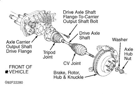
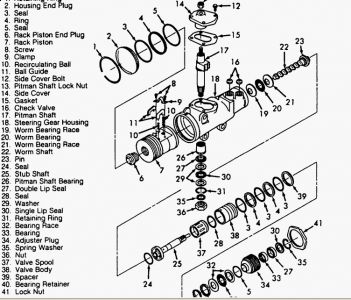
Any leaks in the steering gear above it? Look at the sector shaft seal. Only grease inside the cv-joints, and boot would be split to allow grease to escape.

On the right side it could be the seal, here's how!
RIGHT AXLE TUBE & INNER AXLE SHAFT Removal 1. Disconnect negative battery cable. Raise and support vehicle. Remove skid plate (if equipped). Remove wheel. Remove stabilizer bar from both lower control arms. DO NOT mix left and right stabilizer bar components. 2. Disconnect right outer tie rod end from steering knuckle using Steering Linkage Puller (J-24319-01 ). Wire right outer tie rod linkage aside. 3. Remove stub axle shaft flange bolts from inner axle shaft flange. Turn right wheel outward to loosen stub axle shaft from inner axle shaft flange. Push stub axle shaft toward front of vehicle and wire aside. 4. Disconnect harness connectors for indicator light switch and actuator solenoid at right axle tube. Place drain pan under drive axle. Remove drain plug to drain lubricant. Remove bolts retaining axle tube to right frame. 5. Remove bolts attaching axle tube to axle carrier. Remove axle tube by pulling away from axle carrier to clear shift shaft. While pulling axle tube away, note shifter fork spring location to keep from losing it off end of shifter shaft when removing axle tube. Ensure that open end of tube is pointed upward. Installation 1. If internal carrier components have been changed, see reassembly steps 4) through 9) of RIGHT AXLE TUBE ASSEMBLY under OVERHAUL. If internal carrier components have NOT been changed, clean mating surfaces thoroughly to remove any oil residue. Ensure shift shaft spring is in position. 2. Apply sealant (GM 1052942 or Loctite 518 ) to carrier sealing surfaces. Install axle tube to carrier housing. Install 6 axle tube retaining bolts and tighten to 30 ft. lbs. (41 N.m). Connect stub shaft to inner shaft flange and install 6 bolts. Using a criss-cross pattern, tighten bolts evenly to 59 ft. lbs. (80 N.m). 3. Raise axle tube and install frame-to-tube mounting bolts. On K15/25, tighten nuts to 75 ft. lbs. (102 N.m). On K35, tighten nuts to 106 ft. lbs. (144 N.m). Install tie rod end to steering knuckle. Tighten tie rod nut to 35 ft. lbs (47 N.m). 4. Install stabilizer bar, link, nuts and bolts. Tighten stabilizer bracket-to-frame bolts to 24 ft. lbs. (33 N.m). Tighten stabilizer bar-to-lower control arm nut to 13 ft. lbs. (18 N.m). 5. Reconnect harness connectors for indicator light switch and actuator solenoid at right axle tube. Install differential carrier drain plug, and tighten it to 24 ft. lbs. (33 N.m). Remove differential carrier filler plug and fill drive axle to hole level with SAE 80W-90 GL5 gear lubricant. Tighten fill plug to 24 ft. lbs. (33 N.m). To complete installation, reverse removal procedure. Recheck gear oil when vehicle is on level ground. Fig. 4: Exploded View Of Front Axle Assembly (K15/25 Series) Courtesy of GENERAL MOTORS CORP. Fig. 5: Exploded View Of Front Axle Assembly (K35 Series) Courtesy of GENERAL MOTORS CORP. Page 1 of 1 DRIVE AXLE - FRONT -1994 Chevrolet Pickup K1500 3/27/2009 src="https://www.2carpros.com/forum/automotive_pictures/62217_k1500Right_1.jpg" alt="https://www.2carpros.com/forum/automotive_pictures/62217_k1500Right_1.jpg" />
Friday, March 27th, 2009 AT 7:59 AM


