Hello -
Thanks for the info but you did not give me the 8th digit of your VIN.
I have attached info on changing the multifunction switch.
STEERING WHEEL
Removal & Installation
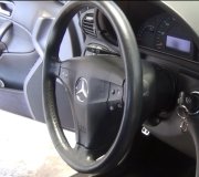
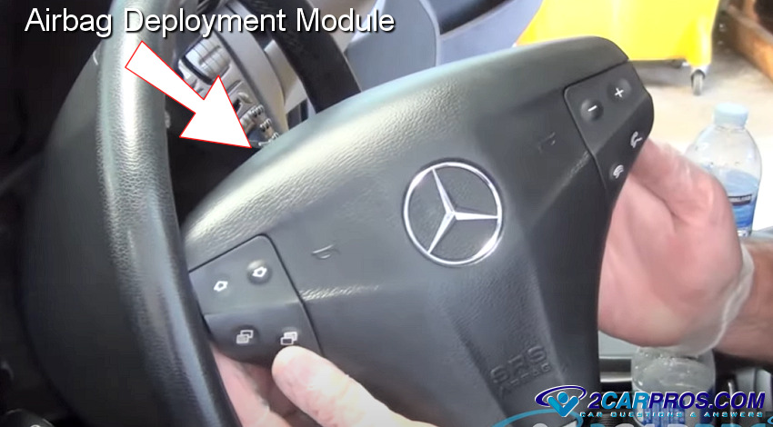
1. Turn ignition switch to OFF-LOCK position. Remove air bag module. See AIR BAG RESTRAINT SYSTEM article. Mark steering wheel hub in relation to slash mark on steering shaft for installation reference. Loosen steering wheel nut, positioning it flush with end of steering shaft.
2. Using Steering Wheel Puller (J-1859-03), pull steering wheel from shaft. Remove steering wheel shaft nut. Remove steering wheel from steering shaft. To install, reverse removal procedure. Tighten steering wheel shaft nut to specification. See TORQUE SPECIFICATIONS .
MULTIFUNCTION SWITCH
Removal & Installation
Ensure lever is in center of OFF position. Disconnect electrical connector behind lever. Remove lever by pulling it straight out. To install, align tab and push lever straight in. Connect electrical connector.
TURN SIGNAL SWITCH
Removal
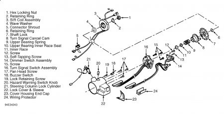
1. Disconnect negative battery cable. Remove SIR coil assembly, and allow it to hang freely. See AIR BAG RESTRAINT SYSTEM article. Remove wave washer. See Fig. 6 .
2. Using Lock Plate Compressor (J-23653-SIR), push down shaft lock and remove shaft lock retaining ring. Discard shaft lock retaining ring. Remove shaft lock. Remove turn signal cancel cam assembly.
3. Remove upper bearing spring, upper bearing inner race seat, and inner race. Remove multifunction lever. See MULTIFUNCTION SWITCH . Push top and bottom edges of end cap out of slots in housing. Tip end cap away from housing, and remove housing cover end cap from vehicle.
4. Remove round washer head and flat-head screws. Remove pivot and pulse switch, and allow to hang freely. Using small screwdriver, pry off hazard warning switch knob.
5. Move turn signal up to right turn position. Remove turn signal switch. Disconnect electrical connector. Remove wiring harness protector. Gently pull wiring harness through steering column.
Installation
1. To install, reverse removal procedure. Tighten screws to specification. See TORQUE SPECIFICATIONS . When installing turn signal cancel cam, lubricate with synthetic grease.
2. When installing shaft lock, ensure inner block tooth of lock is aligned with block tooth of race and upper shaft assembly. Using Lock Plate Compressor (J-23653-SIR), push down shaft lock and install NEW shaft lock retaining ring. Ensure retaining ring is firmly seated in groove on shaft. To complete installation, reverse removal procedure.
Fig. 6: Exploded View Of Upper Steering Column Assembly
Courtesy of GENERAL MOTORS CORP.

I am not sure what you mean when you say brake lights. . .. . ...what is the problem with them?
Wednesday, March 25th, 2009 AT 10:17 PM


