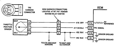
THROTTLE POSITION SENSOR (TPS) Install jumper wires to enable connection of a DVOM in parallel between TPS harness connectors. Connect DVOM positive lead to Blue wire terminal. Connect negative lead to Black wire terminal. See Fig. 10 . Turn ignition on, engine off. Signal voltage should gradually change from less than one volt at closed throttle to about 5.0 volts at wide open throttle position. If reading is not as specified, adjust or replace TPS. See the appropriate ADJUSTMENTS article. A malfunction in the TPS circuit should set a related trouble code. For further information, see appropriate TESTS W/CODES article. Also see TPS adjustment procedure in the appropriate ADJUSTMENTS article in this section.

THROTTLE POSITION SENSOR (TPS) Throttle Position Sensor (TPS) can be adjusted with the use of "Scan" tester or by the following procedure: 1) Install 3 jumper wires between TPS and TPS wiring harness connector. 2) Turn ignition on, engine off. Use digital voltmeter and connect to Dark Blue and Black wire terminals. With throttle at closed position, adjust TPS to obtain specified voltage. 3) Tighten screws and recheck readings. Turn ignition off. Remove jumper wires and reconnect harness connector to TPS. NOTE: All testing procedures are made with engine at normal operating temperature.

SPONSORED LINKS
Sunday, November 29th, 2009 AT 8:59 AM


