Good morning,
There is an inertia switch that is set to open in the event of a roll over or an accident to stop fuel flow.
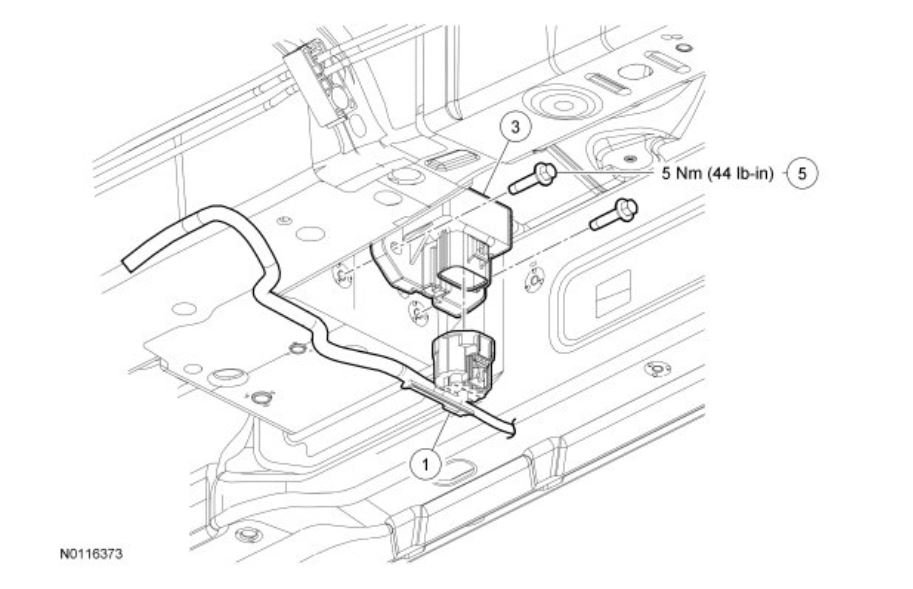
Your car does not list a switch so it is part of the fuel pump control module. It gets an event signal from the Airbag system and turns off the fuel pump.
Roy
Removal and Installation
1. With the vehicle in NEUTRAL, position it on a hoist. For additional information, refer to Vehicle Jacking and Lifting See: Vehicle Lifting > Procedures > Jacking and Lifting.
2. Disconnect the Fuel Pump Control Module (FPCM) electrical connector.
3. NOTICE: Do not overtighten the fasteners or damage to the module may occur.
Remove the 2FPCM (Fuel Pump Control Module) bolts.
- To install, tighten to 5 Nm (44 lb-in).
4. To install, reverse the removal procedure.
Description
Change Vehicle Bookmarks Library Request Conversion Calculator Technician's Reference - Collision
fuel pump
112
Community 3 Create Quote
2014 Ford Truck Edge AWD V6-3.5L
Fuel Systems
Vehicle Powertrain Management Fuel Delivery and Air Induction Description and Operation Components Fuel Systems
FUEL SYSTEMS
Fuel Systems
Overview
The fuel system supplies the fuel injectors with clean fuel at a controlled pressure. The PCM controls the fuel pump and monitors the fuel pump circuit. The PCM controls the fuel injector ON/OFF cycle duration and determines the correct timing and amount of fuel delivered. When a new fuel injector is installed it is necessary to reset the learned values contained in the keep alive memory (KAM) in the PCM. Refer to Section 2, Resetting The Keep Alive Memory (KAM) See: Computers and Control Systems > Diagnostic Trouble Code Tests and Associated Procedures > Resetting The Keep Alive Memory (KAM).
The 2 types of fuel systems used are:
- electronic returnless fuel
- mechanical returnless fuel
Electronic Returnless Fuel System (ERFS)
The ERFS consists of a fuel tank with reservoir, the fuel pump, the fuel rail pressure temperature (FRPT) sensor, the fuel filter, the fuel supply line, the fuel rail, and the fuel injectors. For additional information on the fuel system components, refer to Engine Control Components. Operation of the system is as follows:
1. The fuel delivery system is enabled during ignition ON, engine OFF for 1 second (or until fuel rail pressure exceeds target) and during crank (if fuel rail pressure falls below target) or running mode once the PCM receives a crankshaft position (CKP) sensor signal. Commanded rail pressure is a function of fuel rail and engine coolant temperature, with different values commanded during crank vs. Normal running.
2. The fuel pump logic is defined in the fuel system control strategy and executed by the PCM.
3. The PCM commands a duty cycle to the fuel pump control module.
4. The fuel pump control module modulates the voltage to the fuel pump (FP) required to achieve the correct fuel pressure. Voltage for the fuel pump is supplied by the power relay and fuel pump control module relay. For additional information, refer to Fuel Pump Control - ERFS and Fuel Pump Monitor (FPM) - ERFS.
5. The FRPT sensor measures the pressure and temperature of the fuel in the fuel rail. The PCM uses this information to vary the duty cycle output to the fuel pump control module, which changes the fuel pressure to compensate for varying loads and to avoid fuel system vaporization.
6. The fuel injector is a solenoid operated valve that meters the fuel flow to each combustion cylinder. The fuel injector is opened and closed a constant number of times per crankshaft revolution. The amount of fuel is controlled by the length of time the fuel injector is held open. The fuel injector is normally closed, and is operated by a 12 volt source from either the PCM power relay or the fuel pump relay. The ground signal is controlled by the PCM.
7. There are 3 filtering or screening devices in the fuel delivery system. The intake filter is a fine, nylon mesh screen mounted on the intake side of the fuel pump. There is a fuel filter screen located at the fuel rail side of the fuel injector. The fuel filter assembly is located between the fuel pump and the fuel rail.
8. The FP assembly is a device that contains the fuel pump and the fuel sender assembly. The fuel pump is located inside the reservoir and supplies fuel through the fuel pump assembly manifold to the engine and the fuel pump assembly jet pump.
9. For vehicles with an inertia fuel shutoff (IFS) switch, the IFS switch de-energizes the fuel delivery secondary circuit in the event of a collision. The IFS switch is a safety device that should only be reset after a thorough inspection of the vehicle following a collision. For vehicles without an IFS switch, the fuel pump control module receives an event notification signal from the restraints control module (RCM) to disable the fuel pump in the event of a collision. The signal is sent on a dedicated circuit between the fuel pump control module and RCM.
Image (Click to make bigger)
Sunday, June 23rd, 2019 AT 7:07 AM


