Some more info on operation, for what it may provide:
The brake pedal position sensor is a resistive device used to sense the action of the driver's application of the brake pedal. The brake pedal position sensor provides an analog signal that will increase as the brake pedal is pressed.
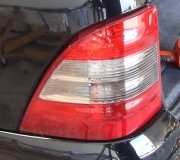
The brake pedal position sensor receives both a 5-volt reference voltage and a low reference signal from the electronic brake control module (EBCM). When the brake pedal is pressed, a variable signal is applied from the brake pedal position sensor to the EBCM through the brake sensor signal circuit. The fuse block left rear supplies battery positive voltage to the bass relay switch through the BASS fuse. One side of the bass relay coil is permanently grounded at G402. The EBCM supplies voltage to the bass relay coil upon receiving the signal from the brake pedal position sensor. The switch contacts of the bass relay close and battery positive voltage is applied through the bass relay switch to the center high mounted stop lamp (CHMSL), and to the turn signal/hazard flasher module through the stop lamp switch signal circuit. The ground for the CHMSL is applied from G402. The turn signal/hazard flasher module then supplies voltage to the left and right stop lamps in the tail lamp assemblies that have ground at G401 and G402. For export vehicles the stop lamps receive battery positive voltage directly from the bass relay.
This is a BPP calibration procedure that involves the use of a scan tool, I don't know if this could be the entire problem:
Brake Pedal Position Sensor Calibration Description and Operation
Calibration Criteria
Brake pedal position sensor calibration must be preformed after the brake pedal position sensor or electronic brake control module (EBCM) have been serviced. The calibration procedure will set the brake pedal position sensor "home" value. This value is used by the EBCM to determine the action of the driver applying the brake system and to provide this information to the vehicle subsystems via the class II communication bus.
Calibration Procedure
"� Install a scan tool.
"� Turn ON the ignition, with the engine OFF.
"� Select Chassis.
"� Select DRP/ABS/TCS/VSES.
"� Select Special Functions.
"� Select the BPP Sensor Calibration and follow the directions displayed on the screen.
Tuesday, June 16th, 2009 AT 1:36 AM


