Buick 1998 suspension overhaul?

257,000 MILES • 3.8L • 6 CYL • 2WD • AUTOMATIC
Avatar
ALPHAA10
  • MEMBER
  • 241 POSTS
Bought front struts and inner and outer tie rods. What else should be installed to restore stable ride?
Apr 15, 2026 at 1:52 PM
Avatar
CARADIODOC
  • ✓Experienced Mechanic
  • 34,398 POSTS
Depends on what's worn out. It isn't customary to just throw a whole bunch of parts at it unless the car has been ignored for a long time. Lower control arm bushings seem to be a popular replacement item on GM front-wheel-drive cars, so check those for looseness or dry-rotting. Anti-sway bar links can wear and cause rattles, but those can wait until later if you aren't sure if they're needed. The car doesn't need another alignment when those are replaced. We only replace loose tie rod ends. Those are not replaced simply for maintenance. If you can get more specific on what kinds of problems you're trying to solve, I can suggest other things to check.

You know an alignment will be needed after parts are replaced, but I have some tricks you can do to make the car easier to drive to the alignment shop. To start with, if the struts are still original, GM didn't provide a "camber" adjustment. That's the inward or outward tilt of the wheel as viewed from in front of the car. Aftermarket replacement struts come with the lower mounting hole slotted to provide for that adjustment, but then where do you set it when installing that new strut? Due to the geometric relationship of the steering and suspension parts, when you move the top of the wheel out on top, it causes that wheel to turn away from the center of the car too. That makes the steering wheel off-center. A simple trick is to use a magnetic angle gauge stuck to the brake rotor. Install a pair of lug nuts to hold the rotor in place. The car needs to be supported solidly on jack stands under the frame rail so it can't shift position. Read the angle on the gauge. Now replace just that one strut. Leave the two lower bolts loose so you can push the spindle in and out on top. Set it so the reading on the angle gauge is the same as you found with the old strut. That step alone will get everything back to close enough to drive to the shop. If you test-drive the car now, don't expect the steering wheel to be straight, but if it's close, you did a good job.

At this point is when I'd replace the tie rod ends on just one side. No measurement is needed. Instead, when you're done on one side, drive the car and see where the steering wheel has moved to. If you find the steering wheel has moved to the left a little, for example, readjust the threaded joint between the inner and outer tie rod end to turn that wheel in the same direction the steering wheel moved to. This may take multiple test drives to get it right, then snug the lock nut. Don't drive the car with that lock nut loose. The road bumps will cause a hammering action on the threads, potentially leading to tearing them off.

When you're done with one wheel, you should end up with no objectionable pull to one side and a reasonably straight steering wheel. Now do the same procedures on the other wheel. The car will still need an alignment. The pickiest thing with alignment angles is tire wear patterns. Even though the alignment may appear to be "close enough", accelerated tire wear can still occur over many miles even when there's no pull and the steering wheel is centered.

If the lower control arm bushings need to be replaced, it's faster and easier to just replace the entire arm. Regardless which way you do it, anytime you have a bushing on parts that rotate, it's important to not tighten the bolts until the car is sitting at its normal ride height. Most of us drive the car with loose bolts through the parking lot to settle those bushings, then we have to crawl underneath to tighten the bolts. I had a drive-on alignment hoist, so it was easy to tighten them with the car in the air. If this doesn't work for you, leave the bolts a little loose, and tell the alignment specialist to check them. If he knows the arms were just replaced, he is likely to double-check those bolts on his own. He will loosen them, bounce the car a few times, then tighten them to specs. When those bolts are tightened while the car is raised up and the suspension is hanging down, it clamps those bushings in a permanent twist when the car is set down on the tires. That twist seriously reduces the life of those bushings.

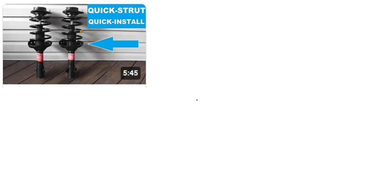
When it comes to alignments, we also get pretty excited about correct chassis ride height. That is definitely sagged from age on your car if the coil springs are original. There's a safety concern working with compressed coil springs when you replace them or when you transfer them to a new strut. The ride height and safety can be addressed by installing a "quick strut". They cost a little more but make the job an easy do-it-yourselfer project needing no spring compressor or special tools. Quick struts come all assembled with new springs, upper mounts, jounce bumpers, and dust shields, making them a simple bolt-on project that takes less than a half hour per side. Ride height was more critical on older rear-wheel-drive vehicles with the "short-long-arm" (SLA), suspension system. Those offered the very best in ride quality, but sagged ride height changed the geometric arcs the control arms went through as the car bounced up and down. The numbers on the alignment computer could look perfect, but there would still be horrible tire wear unless ride height was restored to specs. Let me know if you need those height specs. You can also get them from any tire and alignment shop. They all have very small books that list every model and year, where to take the measurements, and what they should be. For Chrysler products, this involves taking two measurements at each front wheel, subtracting one from the other to get the value. It sounds complicated but it's actually an easy way to compensate in case the vehicle has non-standard tire sizes. For Ford and GM models, they usually provide a chart with a series of height specs. You have to determine the tire diameter to pick the right spec.

GM also uses odd lower strut bolts. The heads have just two flats for a wrench. Those have to be pounded out after the nuts are removed. There's splines under the heads, so they can't be turned or unscrewed. Chrysler used a cam bolt for their lower bolt. Those have offset heads that sit in a pocket formed into the bottom of the strut. As it is rotated, it pushes the wheel in or out making it very easy to get a very precise setting. Aftermarket struts for most GM models come with the same pocket, but you have to buy the special cam bolts. Besides making the adjustments easy, those heads help hold the adjustment in position and prevent shifting from hitting bumps and potholes. There are other bolt designs made for this purpose. You might consider talking with your alignment specialist to see what he recommends.

Let me know if this is what you're looking for or if you have other questions.
Apr 16, 2026 at 6:17 AM
Avatar
ALPHAA10
  • MEMBER
  • 241 POSTS
Thank you for an experience-based review, which provided me several items to consider.

1. The struts are Monroe Quick Struts, and arrived with all huts, with no damaged threads or other anomalies.
2. At this point, I don't know enough to assess worn parts. My Firestone alignment check specialist said I needed struts and inner tie rods, so for good measure,I ordered inner and outer pairs for the front only. (The rear overhaul will be done ASAP, but the front must be done immediately for wheel alignment.)
3. Alignment tips you provided may save me some tire wear before my car arrives at Firestone.
4. Lower control arm bushing replacement is another, experience-based tip, but I wonder how to test for looseness. That step will determine the urgency of replacement.
Apr 16, 2026 at 4:44 PM
Avatar
CARADIODOC
  • ✓Experienced Mechanic
  • 34,398 POSTS
One thing to keep in mind, when inspecting parts, is how the suspension parts are "loaded". That simply means the car has to be jacked up and supported in such a way as to put no forces on the parts. The jack stands should be under the car's frame rails. That lets the tire / wheel hang down freely so you can move them with a pry bar or by hand.

Lets start with the lower control arm bushings. While hanging freely, use about a 2-foot pry bar to move the arms away from the frame they're bolted to. There should be no or very little visible movement. Any movement means they aren't holding that wheel in alignment as the car bounces down the road.

While the wheel / tire is still installed, use them as a handle to turn the steering system left and right a little. This works best with the steering wheel unlocked so you don't feel the normal knocking of the locking mechanism. Tug the tire left and right lightly a couple of times per second. If either the inner or outer tie rod end has looseness, you'll feel the knocking. Next, have a helper do that while you watch or feel underneath to determine if that play is in the inner or outer tie rod end. GM doesn't have a lot of trouble in this area, but the outers wear out more often.

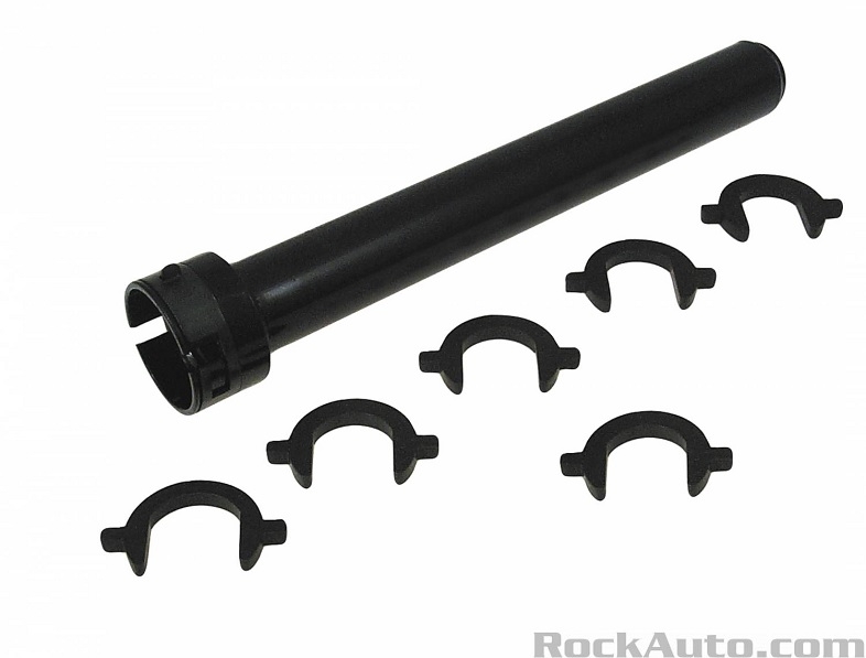
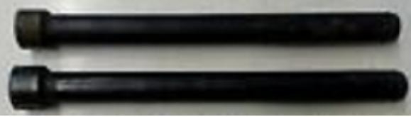
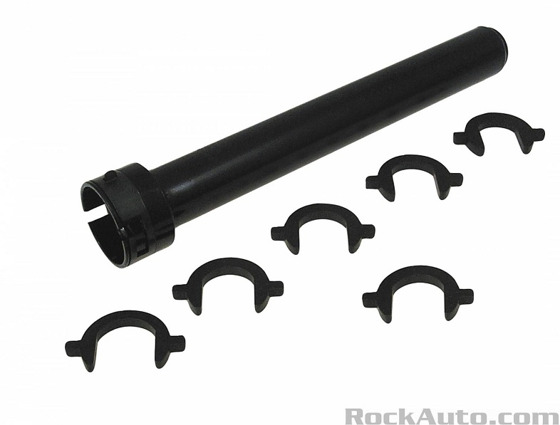
A lot of GM inner tie rod ends require a special socket with a set of different sizes of crow's foot wrenches to grab two flats on the back side of the ball and socket. Check out the first photo. You can borrow that tool from any auto parts store that rents or borrows tools. In my city, they make you buy the tool, then you get a full refund when you return it. If you choose to keep a tool, you still return it, then they order or give you a brand new one. Pick the crow's foot that fits the joint. While holding it in place, slide the socket over it so the two tabs slide into the two slots on the tube. There's a stamped steel ring to rotate that locks the wrench to the tube. Pull out gently on it to keep the wrench on the flats, then use a 1/2" ratchet to unscrew the joint. Normal threads. Turn it counterclockwise to unscrew it. Other tie rod designs require a different special socket to fit a standard hex head around the joint. Those come in two different sizes. Some of them have both sizes built into one tool. All of these are roughly 15" long to slide over the threaded shaft.

Oops, forgot to mention the accordion boot has to be removed first. There's a small spring clamp around the small end. It's common to find a squeeze band around the inner, larger end. Once the ends are snapped together, there's a section to crimp to compress and tighten that band. If you run into frustration trying to stretch them to get them off, and to squeeze them to put it together, . . . welcome to my world. Try whatever you can dream up. At worst you'll have to replace that band. In a pinch, a larger nylon tie strap will do the job. There's a special pliers to tighten the crimp when installing that band. It has a shoe in the middle to push the crimp down. That's mainly for use on CV joints where that crimp could stick up high enough to hit something as the shaft rotates. If you have the room and can fit that pliers in there, it can be used to loosen the band too. Grab the crimped section loosely, then twist the pliers left and right to tug on the crimp. That will stretch it, sometimes enough to allow the band to be unsnapped.

Be aware there's a small metal tube plugged into both of the boots. That just transfers air in them back and forth as you steer. Nothing has to be sealed, but don't forget to pop that back in when the boot is reinstalled.

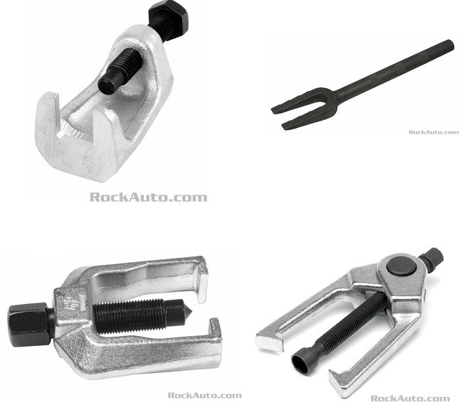
The third photo shows some tools for removing the outer tie rod's tapered stud from the steering arm. An alternative trick is to bang on the side of the arm next to the stud once the nut is removed. The shock is often enough to break the taper.

When you screw the inner and outer ends together, it's okay to use a light coating of axle or wheel bearing grease on the threads. This ensures they're free and not rusted tight for the alignment specialist. Don't use penetrating oil. Many years ago I used Chrysler's "Rust Penetrant" thinking it would be a good rust preventive for vehicles I saw every year for maintenance alignments. What I found was it opened up the threads very nicely, but then it was easy for water to find its way in later and rust developed, making the joint too tight to turn by hand a year later. Now I use Chrysler's "Spray White Lube". That's a lithium-based grease. You can find that at hardware stores under many different names.

Do not use anti-seize compound on anything related to steering and suspension parts. Fasteners tightened to specs will quickly work loose. Same with lug nut studs. Mechanics caught using anti-seize compound on those studs will usually be fired.

Consider making a measurement of the old parts before you remove them, then set the new parts to the same dimension, then tighten the locknut. That will get you close to the correct adjustment. Hand-tight with a regular open-end wrench is sufficient. Those will be loosened to make the "toe" adjustments. Those are always the last two adjustments during the alignment.

To check the lower ball joints, grab the tire and turn it left and right like you did for the tie rod ends, but now tug much harder. You're using the tire as the handle, and you're tugging against the tie rod ends. You need the higher forces to make slop in the ball joint show up. You might have to watch the joint while a helper tugs on the tire. Sometimes this can be a little tricky because the normal, slight turning makes the ball joint's boot turn and falsely look like there's play in the ball and socket. It's better to feel for the looseness. This is another part GM doesn't have a lot of trouble with on their car models.

When you want to check struts, this can't be done now with the suspension hanging down. It's the strut at the end of its travel that's holding everything up. That pressure prevents slop from showing up. What you CAN do for starters is to push the plastic dust boot up, then look around the top of the body where the shaft comes out, for wetness or signs of oil leakage. If you see a lot of caked-on mud, the oil leaked out a long time ago and dust stuck to it, creating that mess. If given enough time for this to occur, it makes for a miserable car to drive, with a lot of bouncing.

This next strut test is a little harder. The car must be jacked up, but not enough for the tire to come off the ground. You just need enough room to reach over the tire, through the coil spring, then under the dust boot. Reach your fingertip up, over the top of the strut body, so it's touching the shaft. With your other hand, tug in and out of the top of the tire. If you feel the shaft walking back and forth, you can be sure the oil has leaked out a long time ago. This too can be a little tricky because you may cause that corner of the car to move up and down a little. The shaft moving up and down can falsely feel like that sideways play. Typically when there's this type of wear, it's pretty evident as there's more than enough play to feel. This type of wear can cause a single knock when turning one way, then another single knock when returning to straight. Bumpy roads make them knock too. This is a rather common cause of elusive knocks that are hard to find.

There's always a hard rubber jounce bumper on the strut's shaft, under the plastic dust boot. Those don't fail or fall off very often. The more common problem is when the spring and other parts are being transferred to a new strut, and that bumper gets overlooked. You don't want to drive a car with that bumper missing. It causes a hard, harsh banging when going over big bumps, such as when entering a driveway. The banging can be bad enough to loosen your teeth!

The upper mounts sit on top of the coil springs and have bearings in them to allow for easier steering. Each mount holds up all the weight of that corner of the car. These caused a lot of clunking over bumps in the 1980s, but lately they don't wear out too often. To check for that wear and resulting looseness, watch the large nut in the center, under the hood, while prying up and down on the tire. If it's bad enough, you'll feel it in the pry bar. A little movement is normal, but I wouldn't want to see more than 1/16" up and down.

There's two more problems with these upper mounts. One is if dirt gets into them, it can make turning left and right feel difficult or have tight spots. That can also cause "memory steer". That's when the steering wheel stays wherever you put it rather than returning freely to center on its own. That makes for a very tiring car to drive. The other problem is some designs have a tendency to break or crumble apart, allowing the strut shaft, and wheel / tire to shift in and out on top a little. That's usually accompanied by a dull thumping sound over bumpy roads. The problem here is that wear is next to impossible to see during an inspection, and it only shows up when the parts are disassembled to be transferred to the new strut. That's when we have to tell you more parts are needed than first thought.
Of course any testing of struts and upper mounts can be ignored since you're replacing them with Quick Struts. You're getting all new parts.

One last thing, especially on older, higher-end Chrysler products, is there's a rubber isolator under the bottom of the coil spring where it rests in the plate welded to the strut body. Those have a steel ring inside to provide support and hold the rubber in place. Over time the rings rust away, then the rubber gets hammered out and deteriorates. That alone lowers ride height by 1/2". You have to get replacements from the dealer. If you choose to leave them out, you have to do that on both sides so the car remains level. Here too, if the car came with them, they will be on the new Quick Struts.

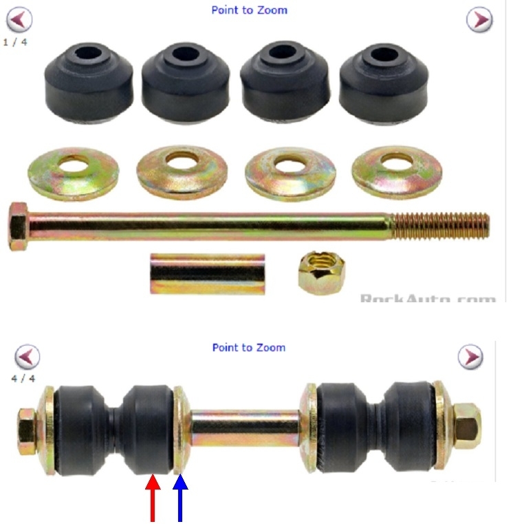
Your model uses the most common anti-sway bar link design. It has been around since forever. See the fourth photo. The top shows the pieces you get in the kit for one link. When these fail, they sound like a tambourine on bumpy roads. Getting the old ones off usually requires an air-powered cutoff tool or an angle grinder. The nuts get rusted tight and commonly round off. The big secret to these is you do not fully tighten the nut when installing them. Rather, run the nut down until the rubbers expand to exactly the same diameter as the steel washers, as shown in the fourth photo, (red and blue arrows), at the bottom. GM used to use shock absorbers with a threaded stud on top, and two rubbers like those shown here. The same applies. When tightening the nut, do so just until the rubbers expand to the same diameter as the metal washers. If those are over-tightened, they'll bind or pinch when that stud needs to tip and swivel a little as the vehicle bounces up and down.

Here's a link to a page with a whole bunch of dandy articles that can explain some of these procedures better:

https://www.2carpros.com/articles

There are also some dandy videos you might want to check out. The second one has to do with struts on a Ford truck, but the information might still apply.

https://youtu.be/OMUFSut2ERA

https://youtu.be/sug_NoHfXG0

Let me know if you have more questions, and please keep me updated on your progress.
Apr 17, 2026 at 11:38 AM
Avatar
ALPHAA10
  • MEMBER
  • 241 POSTS
Wow-- that is a treasury of experience, and I hope others in my situation discover your encyclopedic response. As for me, I'll make sure the jounce bumper is transferred to the new strut. And read carefully your pointers, as I watch the videos.
Cannot thank you enough !
Apr 17, 2026 at 2:26 PM
Avatar
CARADIODOC
  • ✓Experienced Mechanic
  • 34,398 POSTS
Don't worry about the bumpers. They're already on the new Quick Struts.
Apr 17, 2026 at 2:35 PM
Avatar
ALPHAA10
  • MEMBER
  • 241 POSTS
Despite all the urgent tasks I face, it is past time to change the struts and inner AND outer tie-rod ends.
Auto parts stores will loan me some of the tools needed, but the due date for return of the tools probably will find me struggling with a last-minute problem.
So, I am ready to invest in a modest set of tools.
What tools do you suggest for replacing the two struts and inner and outer tie-rod ends?
Any special features I should look for?

* I appreciate the links you provided above
Sep 28, 2026 at 11:34 PM
Avatar
CARADIODOC
  • ✓Experienced Mechanic
  • 34,398 POSTS
If you install quick struts, they come all assembled and ready to bolt on. Just normal wrenches and sockets will do. The two lower bolts have splines under their heads to prevent them from spinning. Remove the nuts, put them back on just finger tight a few turns, then bang on them with a hammer to drive the bolts out. The nuts prevent damage to the bolt threads.

If one of the lower strut bolt holes is slotted, consider buying a pair of "cam bolts". Those were standard on Chrysler models to allow for easy and precise camber adjustment. On GM models, you had to grind one of the holes slotted on the original struts if camber needed to be adjusted, then you just shove the wheel as close to specs as you can get it, then tighten the nuts. Aftermarket cam bolts makes the alignment much easier for the alignment mechanic.

Depending on the style of boot clamp on the large end of the inner tie rod end's boot, you may need the pliers used on CV joint boots. It squeezes a crimp to tighten the clamp. If you hold it on the crimp loosely, then push it side to side, it will open up the old band, then you can unsnap the ends to remove it. Most of the time there isn't enough room for that, then you have to just cut the band and replace it.

Pack some axle grease around the ball and socket of the inner tie rod end. I like to put a very light coating of grease on the threads connecting the inner and outer joints. That prevents water from sneaking in and rusting the threads. Rusted threads make adjustment difficult during the alignment. Don't use anti-seize compound on anything related to steering or suspension parts. That will cause parts to loosen over time.

When you're replacing multiple parts at the same time, there will be too many variables to hope to get camber and the steering wheel back to where they are now. The closest you can get is to count the number of revolutions it takes to unscrew the outer tie rod end from the inner one, the assemble the new ones that same number of turns. Don't expect the steering wheel to be straight, but that will get it close enough to allow you to drive it to the alignment shop without burning the tires off.

You can buy the tools at Harbor Freight Tools. The quality is surprisingly good. If you want to spend more money, look for the Snapon, MAC, or Matco tool trucks. They visit repair shops once a week on a regular schedule. Any mechanic can tell you when they show up at their shop. The tools might be special order because most mechanics already have what they need. Most of the salesmen don't want to carry a lot of special tools that few mechanics are likely to need.

Let me know if you run into problems.

Sep 29, 2026 at 4:07 AM
Avatar
ALPHAA10
  • MEMBER
  • 241 POSTS
Many thanks, CARADIODOC !
Especially useful was your note about cam bolts and CV joint boot pliers.
I already have looked over Harbor Freight, and you are absolutely correct.
Will keep you posted.
Sep 29, 2026 at 10:09 PM
Avatar
STRAILER
  • ✓Experienced Mechanic
  • 55,540 POSTS
Yep, CARADIODOC is one of the sites best! let us know how it goes.
Oct 1, 2026 at 9:05 AM
Avatar
CARADIODOC
  • ✓Experienced Mechanic
  • 34,398 POSTS
You're too kind.

We'll be here when you have an update.
Oct 1, 2026 at 2:11 PM
Avatar
ALPHAA10
  • MEMBER
  • 241 POSTS
On the Buick 98 LeSabre, I believe each strut's upper end needs a small metal "pin" (to prevent twisting?). Where can I find that item?
Oct 8, 2026 at 5:36 PM
Avatar
CARADIODOC
  • ✓Experienced Mechanic
  • 34,398 POSTS
I'm not familiar with the pin of which you speak. And I haven't heard of a twisting problem. I DO know if you try to replace just the strut and reuse the spring and upper mount, you'll save only a little money, but there will be much more time involved, more frustration, a safety concern, and you'll need a somewhat dangerous strut compressor. All told, a "quick strut" is a much better value.

Also, consider that chassis ride height is a variable that affects tire wear and handling, although not quite as much as the alignment. Most conscientious alignment specialists won't take your money or perform an alignment if they aren't allowed to correct sagged ride height. This is a factor of the vehicle's age, not mileage. With quick struts, you get new coil springs that restore the front ride height back to specs. You also get a new upper mount. Those have ball bearings or a plastic disc that supports the weight of that corner of the car while allowing you to turn the steering system freely. Old upper mounts can get rusty, dirty, crack apart, or any other defect you can think of, then they could cause "memory steer". That's where you turn to one side, then let go of the steering wheel and it stays there rather than returning to center on its own. If you've ever experienced memory steer, you won't forget it. It makes for a very miserable and tiring car to drive. You can never take your eyes off the road.

The point of my sad story is there are a whole pile of things you don't have to be concerned with when you use quick struts. They're a fairly simple, bolt-on job. They also include a new "jounce bumper". That's a hard rubber or plastic tube that sits on the strut's shaft. On some car models those are known to deteriorate and crack off. With those gone, a common complaint is a really hard bump when going up a small grade at an angle, such as turning into a driveway that has a pitch to it. The hammering can knock your teeth loose. Quick struts have those new bumpers already installed, along with a hard plastic cover to keep rocks and dirt off the shaft.

The only pin I can think of is back as far as the 1980s, Ford, along with their huge number of really poor steering and suspension designs, had some models like the Fairmont where camber was adjusted by sliding the upper mount left or right. Doing so changed another important, but little-known alignment angle called "steering axis inclination". No spec is ever given for that. It gets measured automatically by all alignment computers, but even a lot of professionals don't know what it is or what it causes. All that is important is it must be very close to equal on both sides for proper handling. Ford's method of adjusting camber on those models changed SAI, which is why it was one of their poor designs. At any rate, they had five drilled holes in the inner fender, and one hole in the upper strut mount. Whichever hole lined up on the assembly line, they tossed a pop rivet in there to hold it in position as the rest of the assembling took place. Later, when they needed to be adjusted, those rivets were drilled out and discarded. Nothing needed to be placed in there later. I've never seen that type of pin on any other car brand or on most other Ford models. If there's something else I'm not aware of, describe it in more detail or post a photo of it if possible.

As for twisting, you may have heard stories of the coil spring not being placed in proper orientation when the old one is transferred to a new strut, or when just the coil spring is being replaced. In fact, the bottom of the spring sits in a pocket formed in the steel plate that's part of the strut assembly. On higher-end models, there' often a rubber isolator between that plate and bottom of the coil spring to insulate road vibration. Once you set the bottom of the spring into its pocket, with the end of the coil butting up to the formed end of the pocket, you set the upper mount on the top of the spring. It also has a plate formed to sit on the spring with the end of a groove, or slot, for the end of the spring to butt up to. Once the upper mount is in place, the large center nut gets tightened on the shaft, but then you will likely have to rotate the upper part of the mount so the three bolts line up with the holes in the inner fender. Don't get excited if you find it really hard to turn that plate by hand. I usually lift the assembly up into the inner fender and install the three nuts finger tight, then grab the spring or strut body and use that to rotate the bottom bracket until it lines up with the steering knuckle. Even though it seems to turn really hard, it will steer perfectly fine. When the end of the spring doesn't line up with the upper mount's pocket or the lower plate's pocket, might be what someone referred to as being twisted.

Another point to look at is the upper mounts on GM front-wheel-drive cars commonly sit at very high angles and offsets. If either end of the spring is not seated in the right orientation, you won't be able to get all three nuts started on top. When you do have the orientation right, the upper mount will drop right into place as you hold the assembly up with one hand while running the nuts on with your other hand, (assuming you have two hands)!

If you do transfer old parts onto a new strut, if the upper mount comes apart in two pieces, don't put any grease in there. Grease up there causes tiny pebbles and road dirt to stick, then those cause binding and that dreaded memory steer.

When the two bolts on the bottom of the strut are removed, I like to block up the brake rotor to hold it and the steering knuckle up. On all front-wheel-drive cars, but GMs in particular, a strong spring inside the inner CV joint pushes the half-shaft out, then, as the rotor falls over, its weight can pull the inner joint out of the transmission, or, depending on the inner joint's design, (and who manufactured it), the inner rollers can come apart. Some of those will never go back together unless you pull the shaft out, take the boot off, then place the dozens of tiny needle bearings back in place. That catastrophe doesn't happen often, but when it does, it can add more than an hour to the job. A lot of inner joints on GM cars are actually pretty hard to get out of the transmission, and most of their joints can't come apart until you take the boot off, so consider this paragraph just something to watch out for, not something you need to plan for.

Keep the questions coming, otherwise, keep us updated on your progress.
Oct 8, 2026 at 10:51 PM
Avatar
ALPHAA10
  • MEMBER
  • 241 POSTS
Thanks, CARADIODOC
Earlier in this process, I had decided to use quick struts, which apparently bypass a host of problems you mention in your post, above.
My reference to a strut pin came from a YouTube video (Chris Fix), and may not apply.to this car. In any case, any strut pin that might exist now is no longer an issue with a remove-and-replace operation..
Will keep you updated, of course..
Oct 12, 2026 at 2:01 PM
Avatar
ALPHAA10
  • MEMBER
  • 241 POSTS
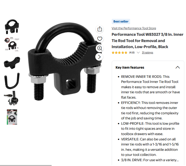
CARADIODOC, in buying an inner tie rod kit, I see the option to purchase only a single U-shaped tool with two bolts, one on each end of the U. But another option provides a set of crow-foot wrenches. Do I need both the U-bolt and set of wrenches?
At first glance, it seems I can buy only the U-bolt and a crow-foot wrench which matches my Buick 98 LeSabre.
Oct 13, 2026 at 12:17 AM
Avatar
CARADIODOC
  • ✓Experienced Mechanic
  • 34,398 POSTS
I'm not familiar with the first one you mentioned. It sounds like it's adjustable for any size flats. I'd be skeptical of that as you may need to use considerable torque to free and tighten that part.

I have two different designs, three tools in total. One is just a six-point socket on the end of a tube long enough to go over the entire inner tie rod end. You turn that with a regular half-inch ratchet and torque wrench. The entire housing of the tie rod end is a giant hex nut. There's two different common sizes of those, so there are two tools to cover all of that design.

As a side note, there were some designs of inner tie rod ends that had an Allen head lock screw that had to be loosened first, and Ford had some with a metal pin that was driven in to prevent the hex from working loose. There were two designs of those pins too. One was removed by threading a thin, tapered tool into the center of the roll pin, then tightening a nut to pull the tool and pin out. The other design looked like a pop rivet with a hardened metal pin in its center. The only way to remove those pins was to forcibly unscrew the joint, and let the threads push the pin out, hopefully without damaging the threads on the steering gear. I haven't seen either of those designs in a really long time. I think both went away after the late 1980s.

Also going back that far, some import models required the new inner tie rod ends to be torqued to achieve a specific pulling force on the outer end of the shaft. That force was measured with a fish scale. Tightening the joint set the tension on the internal spring that put pressure on the ball. Today all inner joints have that spring pressure set during manufacture, so all that's critical is how hard you tighten the hex onto the steering gear.

The second tool design uses those crow's feet you mentioned. That's the much better tool for a rather thoughtless inner tie rod end design. Some engineer didn't realize how much simpler this could have been, but they put the two flats on the backside of the housing where a simple tool won't work. GM is famous for designs that require special tools, and this is one of them. When I bought this tool, the set included six different sizes of crow's feet. Today, I think they're up to eight sizes. Even with this sad design, the engineers can't stick to one common size. If you've never used this tool, you slide the correct crow's foot over the two flats on the back of the joint's housing, slide the tube over the crow's foot with its two tabs mating with the two slot in the tube, then you rotate a metal ring to lock the two pieces together. Pull outward toward you just a little to keep the tool engaged with the flats, then turn it with a ratchet.

it's easiest to start running the new joint on by hand first, as far as it will go, then install the tool and tighten the joint with a torque wrench. The torque spec. is 74 foot-pounds unless specified otherwise in the instructions that come with the new part.
Oct 13, 2026 at 4:00 PM
Avatar
ALPHAA10
  • MEMBER
  • 241 POSTS
Sounds a bit complicated, despite a detailed explanation.
Could I search for the correct tool(s) on any website using the car's description? Or VIN? When I use a browser to search, I get a drop-down list of POSSBLE tool solutions, but no specific match with my car's description.
Most local auto stores do not have anybody who knows the installation process-- they don't want to "waste" time with anything but over the counter sales. .
Oct 15, 2026 at 1:34 PM
Avatar
CARADIODOC
  • ✓Experienced Mechanic
  • 34,398 POSTS
Using the special tool is not complicated as much as it is cumbersome. You can assemble the parts on a workbench to see what it looks like.

In this first photo, it just shows the two regular sockets at the end of long tubes. You need the tool in the second photo. The new tie rod end can be used to see how it works. Pick the crow's foot that fits the two flats on the back of the joint. Slide the tube over the tie rod far enough that the two tabs on the crow's foot slide into the two slots on the tube. At that point you're ready to turn the tube / socket with a ratchet, but you have to be careful to not pull the tube off the crow's foot, or push the crow's foot off the joint. That's what the ring on the tube is for. You rotate that ring to lock the two parts together, then you can pull gently on the tube to keep the crow's foot on the joint's flats. The job would be easier if you had three hands. If you don't, you can expect to experience a little aggravation. You'll need to drop the crow's foot onto the ground at least two times, otherwise you won't have had as much frustration as the professionals experience.

Something else I haven't considered before would be to use a regular crow's foot wrench with a ratchet and long extension. The first problem would be to find a wrench that big, then, for the second problem, I suspect clearance would be an issue. On most car models, there's only a couple of inches leeway to fit the wrench in there, and you have to be able to orient it so it lines up with the two flats.

Another consideration, . . . the car will need an alignment when all the parts have been replaced. You might visit the shop where you plan to take it, and ask the alignment specialist for help. He will have the special tool, and if he isn't busy, might show you how to use it.

The guys who drive the tool trucks from shop to shop can also show you how to use this tool, again, if he isn't busy with other customers. If there are two or more customers waiting in the truck, there's a pretty good chance at least one of them can show you that tool. You can buy the tool there too, but it will cost roughly twice as much as at Harbor Freight Tools. The advantage to buying on the tool trucks is they come to you and they take care of any repairs or exchanges. Most hand tools have a lifetime warranty. Those considerations don't benefit you as you would have to chase them down for service after figuring out their schedule, and many tools from Harbor Freight Tools also have lifetime warranties. This is a tool you're very unlikely to break or damage.

Another possibility is to visit a nearby community college with an Automotive program. The instructor(s) who teach Steering, Suspension, and Alignment can also show you how to use this tool. They may even offer to have the work done in their shop, but it would be on their schedule. In my school, we were always looking for live work to give our kids real-world experience, and we had a couple dozen community members who would sit on a broken car until it fit what we were teaching. In my case, I only taught this subject once per year, for eight weeks, and part of each day was spent in the classroom. We did not do repairs unrelated to what we were currently teaching as that would take work away from the shops that hired our graduates. Labor charge was $10.00 / hour for what the job was supposed to take according to the popular "flat rate" guide, so a job listed as taking one hour would cost you ten dollars, even if it took them a week. The advantage is you get cheap, well-supervised labor. The disadvantage is it will usually take a long time to get your car back. The dollars we collected went into a breakage fund in case we accidentally damaged something. While rare, that damage was more likely to be from difficulty installing a new part. Other repair shops run into the same problem. Getting a replacement new part is paid for by the profits they get on the parts they sell.

I had to squeeze my brain to pop out these ideas. I wouldn't worry about this tool being too complicated to figure out. Once you play with it on the workbench, it will become clear how to use it.
Oct 15, 2026 at 3:04 PM
Avatar
CARADIODOC
  • ✓Experienced Mechanic
  • 34,398 POSTS
I forgot to mention, most auto parts stores rent or borrow tools, and they will have this one. In my city, they make you buy it, then you get a full refund when you return it. If you choose to keep a tool, you still return it, then they give or order you a brand new one.
Oct 15, 2026 at 3:07 PM
Avatar
ALPHAA10
  • MEMBER
  • 241 POSTS
Thanks, CARADIODOC !!
Clearly, you love the craft enough to teach it, and your students are fortunate.

*BTW
Is this tool of any value? Since I plan to install both inner and outer tie rods, this probably will not save me any time.
(Pardon the extra image-- this interface is really awkward, and I found no way under edit to remove the extra. When I selected one of the two, and right-clicked to delete, there was no delete option)
Oct 16, 2026 at 12:01 AM
Avatar
ALPHAA10
  • MEMBER
  • 241 POSTS
CARADIODOC,
Regarding my newly-purchased Monroe Quick Strut (pair)--

Is there a video on actually releasing the Quick Strut safely from its compressed state, once it is bolted into place at the upper (body frame) end? It occurred to me that no video I have seen covers this part of the installation.
Monroe Part Number 171822 (I have recorded many other numbers from the OEM box, if these are important.)
Oct 16, 2026 at 12:43 PM
Avatar
CARADIODOC
  • ✓Experienced Mechanic
  • 34,398 POSTS
I suppose the tool you found would likely work as long as there's room to fit it in there. You'll have to really tighten the two nuts as the joint is perfectly round with no edges or corners for the U-bolt to grab onto.

The old strut assembly is going to be fully extended already when you remove it. You'll likely need a large pry bar to pry the lower control arm down to get the bottom of the strut past it. The car has to be jacked up and supported on jack stands under the frame rails, not under the lower control arms. The strut piston itself is what keeps the coil spring contained and under pressure. If you wanted to remove the spring, such as when transferring it to a new strut, you have to use a strut compressor to compress the spring only an inch or so to relieve the pressure on the strut, then you can loosen the large nut in the center of the upper mount. This is where safety becomes an issue. On almost all other car brands, if you release pressure on the coil spring, it will expand roughly another four or five inches to its free length. If it slips out of the compressor while under pressure, real damage can occur. I had one spring out, make enough racket that the office girls behind two closed doors ran out to see what happened, then it bounced out the garage door and through the parking lot. I saw another one pop straight up and take out an eight-foot light fixture.

The problem with a lot of GM springs, if one jumps out of the compressor, is they usually have a free length of a lot more than another four or five inches. Six to ten inches is common, and most spring compressors can open up far enough to grab it at both ends. That means it can't be compressed enough to fit onto the strut, with the shaft extended enough to allow installation of that large nut. Many wall-mounted strut compressors are able to open up enough to recapture a GM coil spring, but competent do-it-yourselfers don't have those. The more common and inexpensive tool is a clamshell compressor that is operated by turning a large bolt with a wrench. Again, when simply transferring the spring from an old strut to a new one, it is already collapsed most of the way when the compressor is attached. The tool only has to compress it another inch or so, just enough to take the pressure off the upper mount.

Another trick that can solve this problem is to use a pair of compressor bolts that have hooks on each end. There is still plenty of danger involved because of the high angles of the coils. The hooks on this tool tend to keep slipping around the spring, but if you can get them to stay in place, you may be able to compress the spring enough to allow the clamshell compressor to be installed on it. Some people figure out they can use Vice-Grip pliers on the spring to keep the compressor tools from sliding around, but even that is not a good idea. The black paint on the spring is there to protect them from rust. That paint shouldn't be scratched or chipped. Honda had a big problem with that in the 1980s. Rust caused springs to break, usually in the middle, and the really sharp ends created would tear the sidewall of the tire.

As long as the spring doesn't pop out of the clamshell compressor, it can be transferred like any other coil spring, but GM went further and made their spring uncommonly fat, and with odd shapes. Some won't fit inside a clamshell compressor, and some have such weird angles to the individual coils, or "loops", that it's almost impossible to get all four fingers of the compressor wrapped around part of that spring. They just made them really miserable to work with. The safety issue is gone when you install a quick strut since everything is already assembled. Working on GM front-wheel-drive vehicles makes quick struts an even better value and choice.

The new strut is going to come already fully extended in the box. You might be thinking of gas-charged shock absorbers that come strapped in the collapsed condition. While they do self-extend when the strap is cut, that has nothing to do with holding up the weight of the car. You can prove that by collapsing the shock absorber by hand, but you can't hold up that corner of the car. The gas under pressure is just to keep the hydraulic oil from foaming.

You may have also seen new struts that come banded, or strapped, in the collapsed state. That is done solely so they can be shipped in smaller boxes. You can safely cut that strap, then watch as the shaft extends on its own, rather slowly. Here again, you can collapse the shaft by hand, which proves it doesn't hold up the weight of that corner of the car. That's what the spring does.

By the way, I mentioned a while back, . . . having to do with prying the control arm down, that is when the brake rotor likes to flop out and pull the half shaft with it. On GM cars, the inner CV joint doesn't like to pop out of the transmission. It might want to come apart instead, inside the boot. I like to prop the rotor up so that's less likely to happen. If the joint does pop out of the transmission, you won't be able to get the spindle pushed in enough to allow the strut to be bolted to it. Then it's just a matter of working the half shaft around until the joint pops back into the transmission. Don't get excited if the joint pops out and a little transmission fluid runs out. If the car is supported level, very little fluid will be lost.
Oct 16, 2026 at 6:16 PM
Avatar
ALPHAA10
  • MEMBER
  • 241 POSTS
CARADIODOC,
this is what I needed to know--
"The new strut is going to come already fully extended in the box."

I'll keep in mind to support the disk brake rotor, to avoid problems with the CV joint.

Appreciate the pointers, large and small !
Oct 17, 2026 at 2:24 PM
Add a reply
Join 2CarPros for free, one of the most advanced car repair communities on the internet. From first-time drivers to seasoned mechanics, everyone is welcome to reply, share details, and get better answers. You can add a temporary image or video first; uploads are limited to 20 MB.

Frequently Asked Problems for This Vehicle