Hi,
Are you referring to the brake lights or the brakes themselves? If it is the lights, and I have a feeling it is based on your post, lets start with a couple tests.
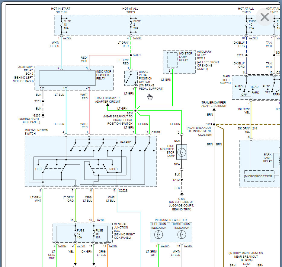
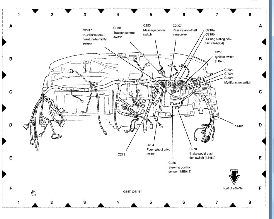
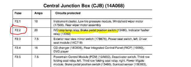
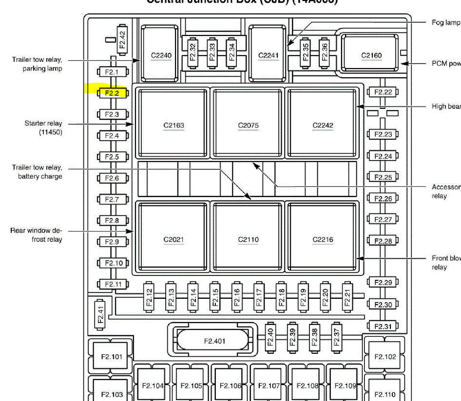
First, I want you to check the fuse I indicated in pics 1 and 2. This fuse powers a few things including the brake light switch. In addition to just checking the fuse itself, make sure there is power both in and out of the fuse.
https://www.2carpros.com/articles/how-a-car-fuse-works
https://www.2carpros.com/articles/how-to-check-a-car-fuse
__________________________________
Now, I suspect the fuse that I mentioned is good simply because the flashers work. However, there is a splice between the fuse where power distributes to the flasher relay and the brake light switch above the brake pedal. So, if the flasher is working, the fuse is good, we either are losing power between the splice and switch or the switch is bad.
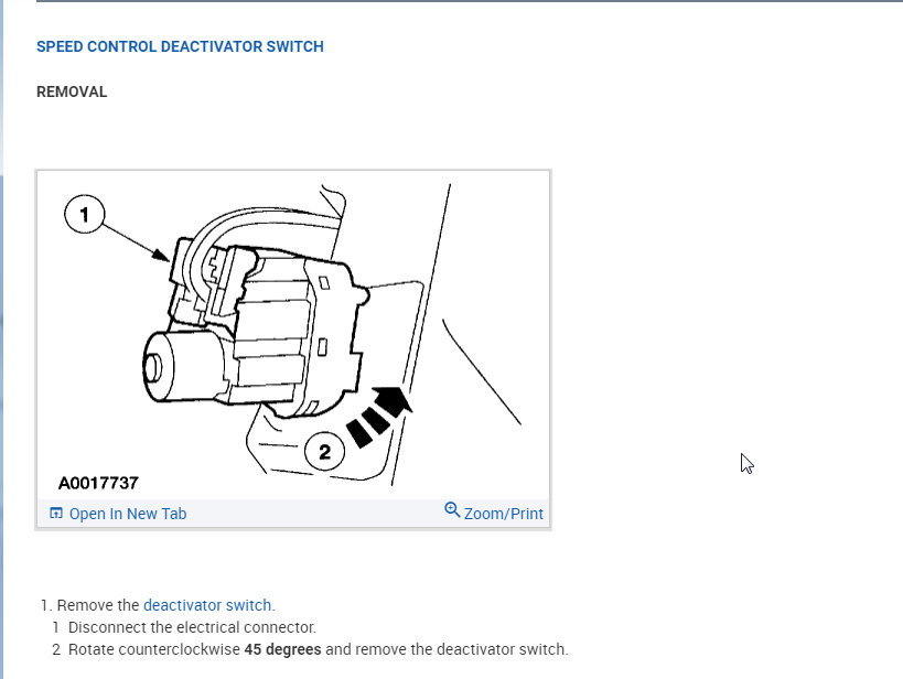
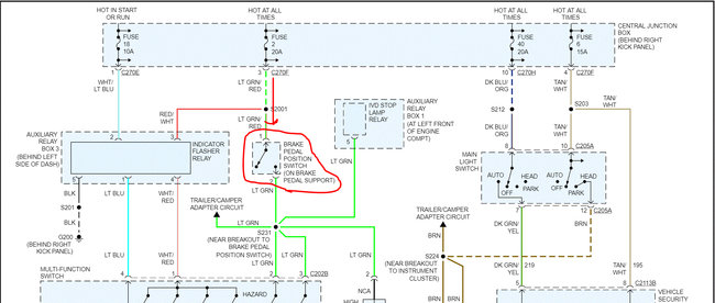
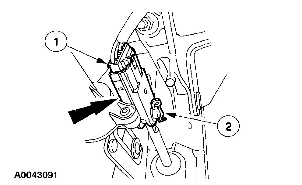
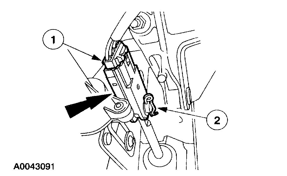
Do, take a look at pic 3. I need you to check for power to the brake light switch. There will be two wires on the switch. One is light green and one will be light green with a red tracer. The one with the tracer should have 12v at all time. Check to confirm there is power to that wire.
If there is power in, then depress the brake pedal and see if there is power out from the switch. If there isn't, replace the switch. If there is power, then we will need to start tracing wires through the multi function switch and then to the lights.
Here are a few links you may find helpful when testing:
https://www.2carpros.com/articles/how-to-use-a-test-light-circuit-tester
https://www.2carpros.com/articles/how-to-use-a-voltmeter
https://www.2carpros.com/articles/how-to-check-wiring
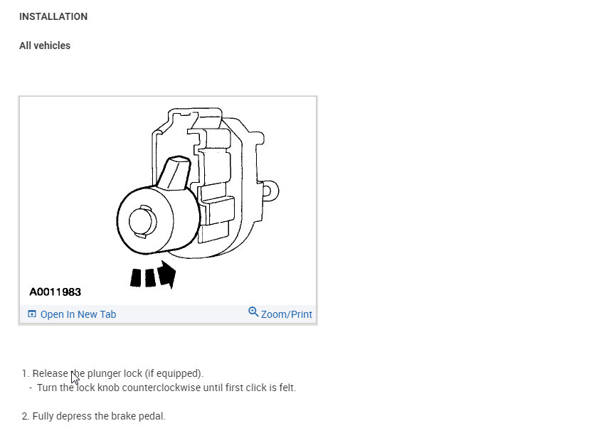
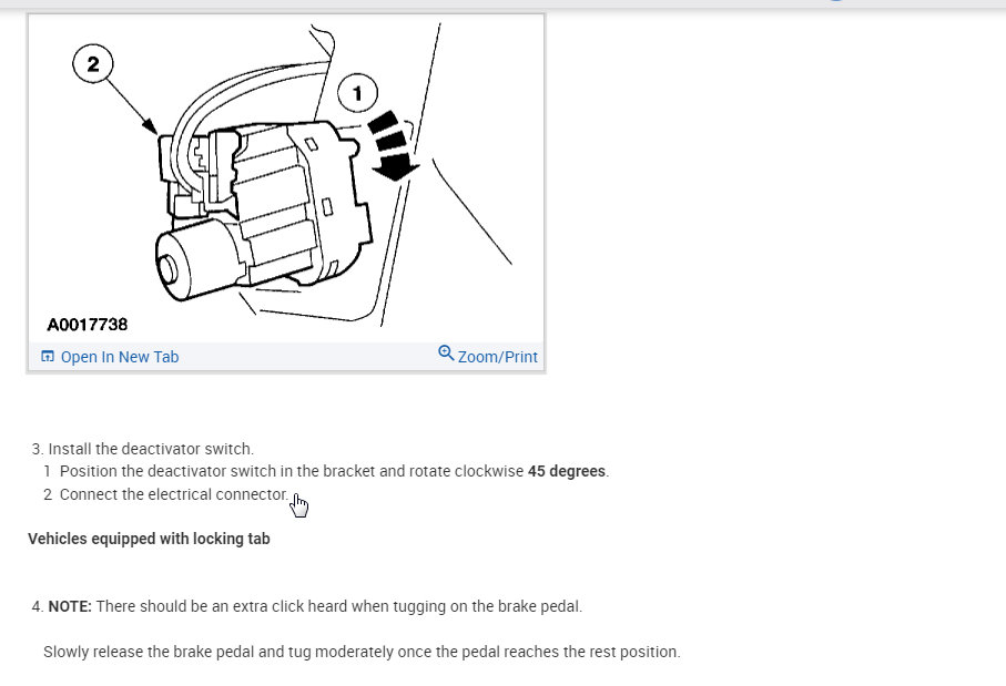
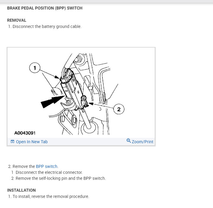
If you find the switch is bad, here are the directions for replacement. The last pic attached correlates with the directions.
________________________________________
2003 Ford Truck Expedition 4WD V8-5.4L SOHC VIN L
Procedures
Vehicle Sensors and Switches Sensors and Switches - Lighting and Horns Brake Light Switch Service and Repair Procedures
PROCEDURES
BRAKE PEDAL POSITION (BPP) SWITCH
REMOVAL
1. Disconnect the battery ground cable.
pic 4
2. Remove the BPP switch.
1 Disconnect the electrical connector.
2 Remove the self-locking pin and the BPP switch.
INSTALLATION
1. To install, reverse the removal procedure.
Let me know what you find or if you have other questions.
Take care,
Joe
Images (Click to make bigger)
Monday, April 13th, 2020 AT 7:36 PM
