Blower motor not working

2007 DODGE CARAVAN
189,000 MILES • 3.3L • 4 CYL • 2WD • AUTOMATIC
Avatar
PUFFNSTUFF
  • MEMBER
  • 59 POSTS
Hello, blower motor not working on my van. Done a few tests and found out I have no power coming from live wire to blower resistor with key on and switch on high. Swap fuses and relay and both are good. I am starting to think I have a fuse box issue.
Thanks!
Jan 31, 2017 at 2:12 PM
Advertisement
Avatar
CARADIODOC
  • CERTIFIED EXPERT
  • 34,308 POSTS
There are two different systems; and both use unnecessarily complicated computer controls. The fan is wired differently than on older systems. twelve volts is applied directly to the fan motor from a "front fan relay". Check for that twelve volts on the black wire at the motor.
Jan 31, 2017 at 2:26 PM
Avatar
PUFFNSTUFF
  • MEMBER
  • 59 POSTS
Thanks. Checked it by connecting voltmeter and shows no voltage. Fan works fine when tested directly to battery. Thanks!
Jan 31, 2017 at 2:34 PM
Advertisement
Avatar
CARADIODOC
  • CERTIFIED EXPERT
  • 34,308 POSTS
Do you have dual zone front heating?
Jan 31, 2017 at 3:27 PM
Avatar
PUFFNSTUFF
  • MEMBER
  • 59 POSTS
No
Feb 1, 2017 at 6:43 AM
Avatar
CARADIODOC
  • CERTIFIED EXPERT
  • 34,308 POSTS
If there's no 12 volts on the black wire, look for the "front fan relay" in the under-hood fuse box. Bypass that relay, then see if the fan motor runs. You can do that by removing the cover from the relay, then reinstalling it that way and squeezing the contact, or use a stretched-out paper clip or piece of wire to connect terminals 30 and 87 together in the socket.
Feb 1, 2017 at 2:45 PM
Avatar
PUFFNSTUFF
  • MEMBER
  • 59 POSTS
Thanks! I'll give it a try..
Feb 1, 2017 at 8:05 PM
Avatar
PUFFNSTUFF
  • MEMBER
  • 59 POSTS
Hello! Here's what I done so far. I removed the 40amp fuse and hooked a jumper wire from fuse pin to positive on battery and everything works..I swapped fuses and the fuse is good and I also swapped the relay to the starter relay and it worked so I am guessing the really should be fine also.. All this leads me to believe that I have a fuse box issue.. Am I correct in saying this..thanks!
Feb 2, 2017 at 11:22 AM
Avatar
CARADIODOC
  • CERTIFIED EXPERT
  • 34,308 POSTS
Hooking a jumper wire between the fuse socket and battery is the same as jumping the two relay terminals 30 and 87 together. All this proves is that relay is not being turned on, and that is done by an unnecessarily-complicated computer circuit. It does prove the rest of the fan circuit is working.

Check for 12 volts on terminal 30 in the relay socket. It should be there all the time.

Which engine do you have, the 3.3L V-6 or the 2.4L four-cylinder?

Feb 2, 2017 at 12:48 PM
Avatar
PUFFNSTUFF
  • MEMBER
  • 59 POSTS
3.3. So is it possible it could be the Fcm module attached to the fuse box? I am not sure but I believe I had power at 86 and 87 but none at 30.. I will have to double check that..I have heard that this Fcm module provides ground to circuits..i will check what you mentioned also..so you are saying the really is not turning on? Thanks!!
Feb 2, 2017 at 1:23 PM
Avatar
CARADIODOC
  • CERTIFIED EXPERT
  • 34,308 POSTS
There is no 12 volts being switched onto the line to the fan motor. That can be because there is no 12 volts feeding the relay or because the relay is not being switched on.

You're right about the grossly-over-complicated fuse box. That is a ridiculous Ford innovation that everyone else copied. It truly does replace simple, reliable switches with unreliable computer circuits.

Jump terminals 30 and 87 together right in the relay's socket. If the fan runs, there has to be 12 volts getting to terminal 30, and there's no need to look further. If the 12 volts is indeed missing on terminal 30 I'd be real surprised because the circuit that feeds the fan relay also feeds all the other functions. There would have to be a break inside the module, and that would be very uncommon.
Feb 2, 2017 at 4:03 PM
Avatar
PUFFNSTUFF
  • MEMBER
  • 59 POSTS
I'm confused.. Do I jump 87 and 86 by this diagram or 86 and 30? And if I do jump them and it works does it confirm I have a fuse box issue? 86 is battery voltage coming in and 87 is voltage coming out and going to fuse.. Is this correct? This is the correct diagram I take i?. Thanks!!
Feb 2, 2017 at 4:45 PM
Avatar
CARADIODOC
  • CERTIFIED EXPERT
  • 34,308 POSTS
Nope. Jump 30 to 87. That is connecting the two switch contact terminals. 85 and 86 are the control half of the relay, and is where I suspect we're going to find the problem.
Feb 2, 2017 at 5:13 PM
Avatar
PUFFNSTUFF
  • MEMBER
  • 59 POSTS
Okay, thanks a million! I will try it.. I live in a cold and snowy climate with no garage and I am doing this in between the weather and work.. I will post once I try it.
Feb 2, 2017 at 5:23 PM
Avatar
PUFFNSTUFF
  • MEMBER
  • 59 POSTS
Will I proceed any further if this does'nt work?
Feb 2, 2017 at 6:30 PM
Avatar
CARADIODOC
  • CERTIFIED EXPERT
  • 34,308 POSTS
Once you verify the high-current part of the circuit is working, where we go next depends on what I can find in my research of circuit operation. I prefer to follow wiring diagrams to the source of the problem, but when these over-complicated computer controls are added to what used to be common-sense circuits, there are no clear-cut tests that will provide useful information.

I'm in the middle of Wisconsin, so I know very well what working in cold is like.
Feb 3, 2017 at 2:26 PM
Avatar
PUFFNSTUFF
  • MEMBER
  • 59 POSTS
I'm in Newfoundland Canada..I never tried anything today whereas I have been working most of the day but I will be checking it again tomorrow.. I will try jumping pins 30 and 87 like you mentioned.. I will let you know of my findings. anything else I should check while I'm at it? .thanks for the help!
Feb 3, 2017 at 6:31 PM
Avatar
CARADIODOC
  • CERTIFIED EXPERT
  • 34,308 POSTS
If the fan runs, the next thing is to figure out why the relay is not being turned on. Terminal 86 should also have 12 volts all the time. The computer grounds terminal 85 to turn the relay on. The data buss wire is the only thing I can find that connects the heater control assembly to the Integrated Power Module. That means further testing requires a scanner.

The first step with the scanner is to access the heater control module and see if it shows it is sending a signal for "fan control" when any functions are selected. If it is sending that signal, the next step is to access the Integrated Power Module and look at the "Inputs / Outputs" to see if it is receiving and recognizing that signal. If it shows the signal is being received, but it's not turning on the relay, that IPM is suspect.
Feb 3, 2017 at 6:51 PM
Avatar
PUFFNSTUFF
  • MEMBER
  • 59 POSTS
Okay.. Will do.. Thanks! So it is possible I may need a fuse box? After performing these tests?
Feb 3, 2017 at 7:41 PM
Avatar
PUFFNSTUFF
  • MEMBER
  • 59 POSTS
Okay.. I tried jumping pins 87 and 30 and it worked.. Blower was running on all speeds and from what I have been hearing and reading leads me to believe that the Fcm ain't sending a ground signal to pin 85 of the relay. Broken wire maybe? If I was able to find which Fcm pin that pin 85 of the relay goes to I should be able to check continuity between those two pins. Is that correct? I haven't removed any of that yet to check, but planning on removing it next chance I get..thanks for your help! Much appreciated..
Feb 4, 2017 at 9:58 AM
Avatar
CARADIODOC
  • CERTIFIED EXPERT
  • 34,308 POSTS
Nope. The only thing shown on the diagram is a box representing the computer circuitry that grounds the relay. You need the scanner to figure out if the heater controller is sending the "fan request" signal or the front module is not reacting to that request.

To bypass the computer controls, you can stick a thin wire into terminal 85, then install the relay. Use a jumper wire to ground 85, and the fan will work. The jumper wire is taking the place of the computer controls. Nothing else will be damaged, but I don't know what the ramifications are of doing that as far as setting diagnostic fault codes.

Be careful to not use such a fat wire as to spread the terminal in the socket. That can cause intermittent problems later.
Feb 4, 2017 at 3:51 PM
Avatar
PUFFNSTUFF
  • MEMBER
  • 59 POSTS
I'm after trying 2 other heater controls before I posted the problem and still nothing.. Going to get pretty cold here now for the next few days so may be awhile before I get back at it again..I will try what you mentioned though.. Can I rule out heater control if I was after trying 2 others so far? Thanks!!
Feb 4, 2017 at 4:18 PM
Avatar
CARADIODOC
  • CERTIFIED EXPERT
  • 34,308 POSTS
Probably can rule out the controllers, but it still makes sense to use a scanner to see what's going on. There could be a power, ground, sensor, or actuator circuit problem that is preventing the controller from generating the "fan request" signal. Admittedly, it's looking more like the problem is with the Integrated Power Module, but we'd like to know that for sure before wasting money on a new one.
Feb 6, 2017 at 3:06 PM
Avatar
PUFFNSTUFF
  • MEMBER
  • 59 POSTS
I agree.. I can take my chances and pick up an ipm at a scrap yard for $35 with the Fcm included..I also read that I can check resistance from pin 30 of the Fcm to relay ground pin....is this possible? ..Haven't been at it lately.. it's been -24-25 windchills here this past few days. Suppose to warm up in the next few days... Thanks
Feb 7, 2017 at 5:08 PM
Avatar
CARADIODOC
  • CERTIFIED EXPERT
  • 34,308 POSTS
Nope. Forget terminals 30 and 87. You already verified that entire part of the circuit is working when you bypassed the relay and the fan ran.
Feb 8, 2017 at 7:24 PM
Avatar
PUFFNSTUFF
  • MEMBER
  • 59 POSTS
Pin 30 on the Fcm sends a ground signal to terminal 85 of the relay..is this correct? Can I check continuity between these two points for broken wire? Whatever is going on the relay is not receiving ground signal from Fcm for some reason..milder here tomorrow so I will go at again for awhile.. Thanks!!
Feb 8, 2017 at 10:06 PM
Avatar
PUFFNSTUFF
  • MEMBER
  • 59 POSTS
Hi! I removed the fuse box and this is what I discovered.. Bit of corrosion and the bottom left plugin has a pin still left in it from the connector..not sure if you can notice it in the pic..I'm more and more starting to believe this is the issue.. Thanks!!
Feb 9, 2017 at 11:59 AM
Avatar
PUFFNSTUFF
  • MEMBER
  • 59 POSTS
Don't look the best
Feb 9, 2017 at 3:20 PM
Avatar
CARADIODOC
  • CERTIFIED EXPERT
  • 34,308 POSTS
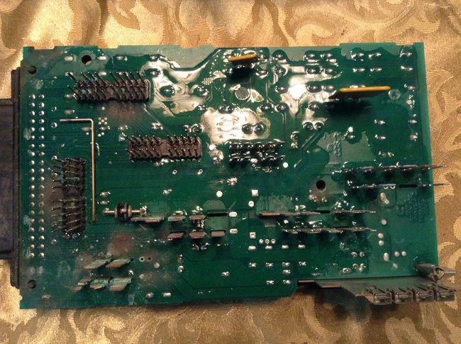
!!!!!!!!!! You found the cause of the problem! I'm so happy because there is a chance we can fix it.

I'm not sure which terminal you're referring to, but I see a bunch that need attention. The first step is to shine up the ones near my nifty arrows. If this would be on a tv or vcr, I would just unsolder the corroded terminals and replace them, but I don't recommend that for car computers unless there is no other choice but to junk it if it doesn't work. I used to purposely install a lot of electrical defects, ("bugs"), for my students to diagnose. One of them was a break in a copper trace on the Engine Computer for a '94 Intrepid. The bug was to simulate a failed voltage regulator. I drilled a hole through the board to run a wire to a switch, so the kids could switch the defect in and out as desired. I found out that some of these boards have more than the common copper traces on both sides. This computer had two additional layers sandwiched in the middle, and I drilled right through the circuit that ran one of the injectors. To avoid that potential problem with your computer, if there isn't enough terminal left to shine up, I would try to find a little remaining tab to solder a new terminal to. If that is not an option, solder a pigtail wire to the board, then run that out and attach it to the wire in the plug.

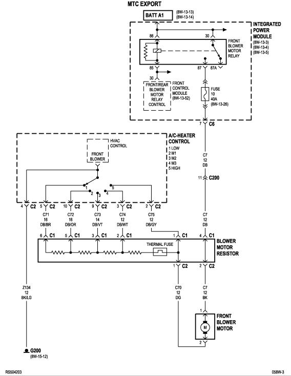
You're still confusing the function of the relay's terminals. 30 and 87 are the two contacts of the switch. They have nothing to do with 85 and 86. Those two are for the electromagnetic coil that runs the contacts. 30 and 87 are switching 12 volts on and off that goes to the fan motor. 86, (I think) or 85 gets 12 volts applied, and the other one gets grounded, (0 volts), to cause it to create the magnetic field that turns the contacts on. Those two circuits, (30 and 87), and (85 and 86), have nothing to do with the operation of the other one. In this case, one coil terminal and one contact terminal each have 12 volts applied, so for convenience, they are tied together inside the computer. That is simply done to reduce the number of wires going to the computer by one. For comparison, you can say the wipers and the radio both have 12 volts applied, so they could be run on the same wire, but the two systems are not related.

Where I added confusion to the story is when discussing the coil circuit in the relay. It needs 12 volts across it to operate. That means 0 volts on one terminal, (ground), and 12 volts on the other. Both are needed to turn the relay on and either one can be removed to stop it from turning on. Since 12 volts is applied to one coil terminal all the time, it is necessary to remove the ground to turn it off. That is actually how most computer-controlled circuits do the on / off switching. What is missing here is we aren't getting the ground on the coil terminal to turn the relay on, and that, I'm pretty sure, is due to the corroded terminals.

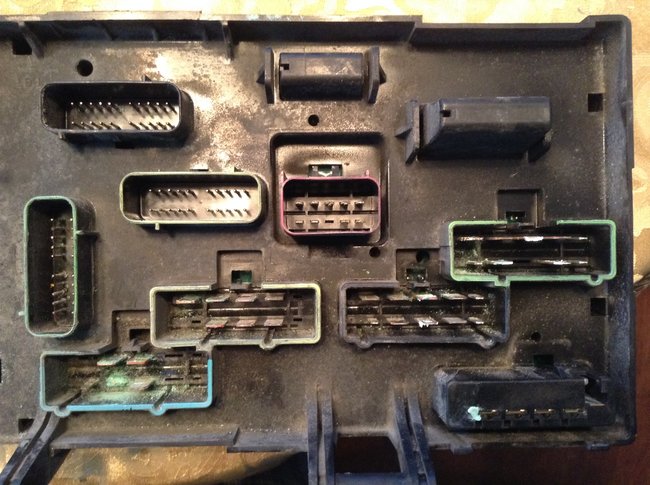
You're also going to have to address the mating terminals in the connectors. Given the extremely excessive amount of corrosion, I suspect it doesn't even pay to try to shine them up, then squeeze them tight to make solid contact. Where I would start is by snipping off the needed plugs from a similar vehicle in a salvage yard, then experiment on those first. There will be a locking wedge of a different color, often red, white, yellow, or blue, that must be pried out, then there will be some means of lifting a plastic finger to allow the terminal to be pulled out. You can use one of those terminals to install in your connector body, then splice the wires, or you can buy the correct terminals from the Chrysler dealer's parts department. GM has huge replacement terminal kits specific to each of their car models. Chrysler has every terminal available by the bag. In either case you just buy the number of terminals you need. They can even pick out the correct terminals for you based on application, without you even supplying an old one for comparison. Using original terminals insures they will clip into the connector body and remain firmly seated. When you have a melted connector body, as in an overheated ignition switch or head light switch, you can cut the melted part out, reinstall it that way, then solder on universal replacement crimp-on terminals and plug them in individually.

The reason I want you to practice on a salvage yard connector first is I also ran into a problem on a '97 Dakota. I made a REALLY big deal that no one was ever allowed to pierce a wire's insulation to take a voltage reading, and when I found someone had done that, they got the privilege of replacing that piece of wire, partly so moisture would not get in and corrode the wire, and partly so that poke mark did not become an illegitimate clue for the next person who was going to diagnose this bug. To replace a wire in one of the connectors for the Engine Computer, the terminal had to be removed so the new wire could be crimped and soldered to it. These connectors caused a whole new degree of frustration when trying to reassemble the terminals into the body. It took me more than a few hours to get one back together. I suspect there was some easier way to do it, but I never figured it out. I don't want you to pull your hair out if you have that same style of plug.

As long as I'm sharing all this wondrous information, Chrysler was real good to my Automotive program. The Intrepid was one of about 50 used to evaluate and fine tune a new assembly line. The Dakota was used by their head of training for all of Wisconsin and the UP for about six months. They didn't want either of those released to the public because they had been poked and prodded on so much. Instead, they donated them to one of three college programs they used for their remote training centers. Later, they even built an '03 Durango specifically destined for my program. We received it with less than three miles on it. Thank you, Chrysler.
Feb 9, 2017 at 5:07 PM
Avatar
PUFFNSTUFF
  • MEMBER
  • 59 POSTS
Thanks for all the communication on helping me out. The red arrow you drew pointing to a bad terminal.That terminal is completely broke of at the base.. Going to see if I can pick up a used one somewhere and try it out, Have nothing to lose I guess..don't know much about electrical just some basic stuff, hence the understanding of the relay .do you know if I will have to program the other one? Thanks for your help!
Feb 9, 2017 at 6:39 PM
Avatar
CARADIODOC
  • CERTIFIED EXPERT
  • 34,308 POSTS
I never got involved with programming 'puters. I have a rebuilt 2014 Ram truck now, but it was driveable when I bought it, and didn't need any electrical repairs. You might look for a local tv repair shop. The people there are good at soldering and coming up with make-shift repairs.
Feb 9, 2017 at 7:36 PM
Avatar
PUFFNSTUFF
  • MEMBER
  • 59 POSTS
I am happy to announce that it is fixed.. Got a fuse box with Fcm included at a scrap yard for $40.00.installed it and everything worked fine.. I like to thank you for your guidance with this..thank you so much for your help..
Feb 10, 2017 at 11:34 AM
Avatar
CARADIODOC
  • CERTIFIED EXPERT
  • 34,308 POSTS
Dandy! Can I assume the new module did not need to be programmed to your vehicle?
Feb 11, 2017 at 12:09 PM
Avatar
PUFFNSTUFF
  • MEMBER
  • 59 POSTS
Nope. It was already on the other fuse box.. Just installed it connected the plugs installed battery and that was it.. Maybe because I replaced the whole thing, fuse box and Fcm together as a unit..
Feb 11, 2017 at 4:02 PM
Avatar
STRAILER
  • CERTIFIED EXPERT
  • 53,855 POSTS
Glad you could get it fixed please use 2CarPros.com anytime we are here to help

Best, Ken
Feb 15, 2017 at 9:56 AM
Avatar
SLINGELBAUGH
  • MEMBER
  • 1 POST
I have a 2007 Dodge Caravan and yesterday, the fan/heater in the front of the van stopped working. The back blower/heater still works, just not the front. Any idea what it could be or how to fix it?

Thanks!
Nov 3, 2020 at 9:07 AM (Merged)
Avatar
MASTERTECHTIM
  • CERTIFIED EXPERT
  • 4,750 POSTS
check for power and ground at the motor, if thats good you need to replace the motor.
Nov 3, 2020 at 9:08 AM (Merged)
Avatar
DAVIDCAMPBELL
  • MEMBER
  • 1 POST
2007 Dodge Caravan/ where is the relay for the blower? Part Number?
Nov 3, 2020 at 9:08 AM (Merged)
Avatar
HMAC300
  • CERTIFIED EXPERT
  • 48,601 POSTS
we dont' have part numbers but the relay shoud be in the integrated power module. pic enclosed
Nov 3, 2020 at 9:08 AM (Merged)
Avatar
KLESTER09
  • MEMBER
  • 1 POST
The front blower motor just quit working no noises nothing
Nov 3, 2020 at 9:08 AM (Merged)
Avatar
JACOBANDNICKOLAS
  • CERTIFIED EXPERT
  • 110,175 POSTS
The front blower motor is under the dash on the passanger side. You need to start by checking to see if there is power to it. If there is, the motor is most likely bad. If there is no power, you need to work back through the resister, relay, and to the switch to see where power is lost.
Nov 3, 2020 at 9:08 AM (Merged)