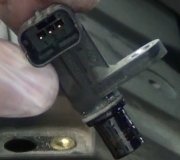
The wiring diagram for the SVT has the 3 wire connector at the bottom left of the diagram. It is connectoer S252. The Non SVT or ZX3 has the speed sensor in same position on engine harness, right side of transmission, but it is a 2 wire speed sensor. It is at the bottom left of the second wirng diagram in the second post window.
The difference is that the Black/Orange wire on the SVT is a ground wire. It also sows the SVT speed sensor as a resistor. The ZX3 does not indicate the type of component, so it might be a propietary control box.
It is hard to say if you can hook up the Blue/White wire and the Brown/Blue to the Green Red wire and ground the other wire.
This is for an automatic transmission and will affect the performance, probably making it where it is undriveable.
I would have to research a bit more to see if there is a work around to make the output signals match. This would take some time.
If you can confirm that the harness matches in regards to the speed sensor. For example, if every connector is hooked up, is that the only thing not hooked up and can you look at SVT engine and see if you can trace a ground for the Black and Orange wire.
There might be a way to do it, it just makes it tough if the ZX# is a control unit with a non-linear signal while the SVT is a resistor with a linear signal.
Just knowing teh specifications for testing is not enough as that only tests one certain point or two, min/max, and does not test the output in between.
The only way to see if it works is to do it. You might risk damaging the ZX# control unit though.
Attached to this post is the SVT and the next post will be the ZX3.
Image (Click to make bigger)
Wednesday, October 5th, 2011 AT 4:29 AM


