P0888= " Less than 3 volts at trans control relay output terminals at TCM, after TCM energizing relay" Relay off should be less than 3 volt before TCM turns it on.
P0700= DTC P0700: EATX CONTROLLER DTC PRESENT
Monitored & Set Conditions
Electronic Automatic Transaxle (EATX) controller is monitored for DTCs when ignition is on and
engine is running. EATX controller may also be referred to as Transmission Control Module (TCM).
DTC will set in Powertrain Control Module (PCM) memory if any DTC is set in the TCM memory.
Possible cause for DTC to set is: TCM DTC is present in PCM.
Testing
Turn ignition on. Using scan tool, read DTCs. If DTC P0700: EATX CONTROLLER DTC PRESENT
is set, this DTC indicates a transmission DTC has previously been set. A DTC may not currently be
present in TCM if a transmission repair was performed. If after reading transmission DTCs there are no
DTCs in TCM, this DTC may be erased from PCM. If a TCM DTC is present, see appropriate
DIAGNOSIS article in AUTOMATIC TRANSMISSIONS. If no TCM DTCs are present, test is
complete.
P0888: Possible Cause
Low battery voltage.
Open fused B+ circuit to transmission control relay.
Open ground circuit.
Transmission control relay output circuit shorted to ground.
Open transmission control relay circuit.
Defective transmission control relay.
Malfunctioning TCM.
Diagnostic Procedure
1. Using scan tool, check STARTS SINCE SET counter. If counter is equal to zero, go to next step.
If STARTS SINCE SET counter is not set to zero, go to step 9.
2. Turn ignition off. Remove transmission control relay from PDC or IPM (as applicable). Turn
ignition on. Connect test light between ground and terminal No. 6 (fused B+ circuit) at relay
connector. See WIRING DIAGRAMS. If test light is illuminated brightly, go to next step. If test
light is not illuminated brightly, repair transmission control relay fused B+ circuit for high
resistance or open.
3. Turn ignition switch to LOCK position. Disconnect TCM connector. Using DVOM, measure
Tips Click a link to view tip
CruisinMiles Tip: DTC P0888
NOTE: Ensure PRE-DIAGNOSTIC CHECK has been performed before proceeding
with the following procedure. Always perform VER-1A: VERIFICATION
TEST after repairs are complete.
NOTE: Compare brightness of test light connected directly to battery
during following test steps.
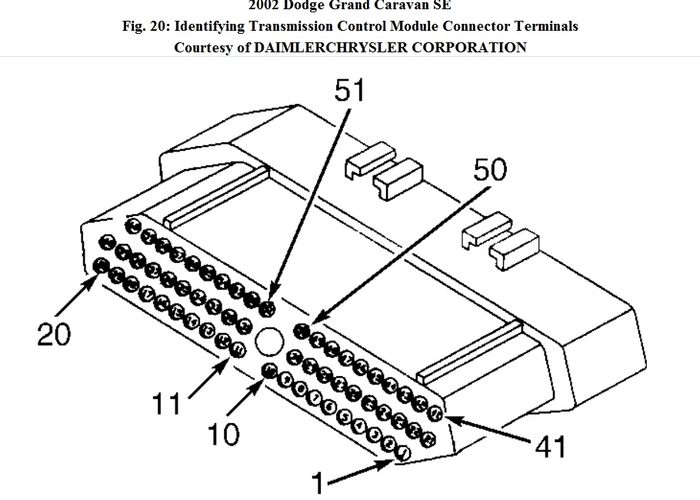
Resistance between TCM harness connector terminals No. 15, 16 and 17, and corresponding relay
connector terminals. See WIRING DIAGRAMS. If resistance is greater than 5 ohms on any
circuit, repair open in suspect relay output circuit. If resistance is 5 ohms or less on all circuits, go
to next step.
4. Ensure ignition is off. Using test light connected to battery voltage, probe terminal No. 2 (ground
circuit) at connector. If test light illuminates brightly, go to next step. If test light does not
illuminate brightly, repair ground circuit for high resistance or open.
5. Disconnect TCM harness connector. Disconnect transmission solenoid pack harness connector.
Connect fused jumper wire between fused B+ circuit and transmission control relay output circuit
at relay connector. See WIRING DIAGRAMS. Using test light connected to ground, probe
terminals No. 16 and 17 (transmission control relay output circuits) at TCM harness connector.
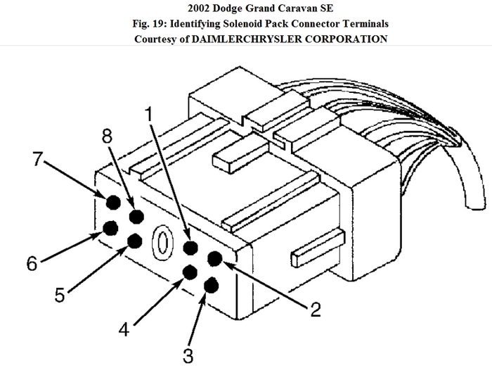
Probe terminal No. 4 at transmission solenoid harness connector. If test light illuminates brightly
at all terminals, go to next step. If test light does not illuminate brightly on any circuit, repair
suspect transmission control relay output circuit for high resistance or open.
6. Measure resistance between ground and terminals No. 16 and 17 (transmission control relay
output circuits) at TCM harness connector. Measure resistance between ground and terminal No. 4
at transmission solenoid harness connector. If resistance is less than 5 ohms on any circuits, repair
suspect transmission control relay output circuits for short to ground. If resistance is 5 ohms or
greater on all circuits, go to next step.
7. Measure resistance between ground and terminals No. 15 (transmission relay control circuit) at
TCM harness connector. If resistance is less than 5 ohms, repair transmission relay control circuit
for short to ground. If resistance is 5 ohms or greater, go to next step.
8. Install substitute transmission control relay. Turn ignition on. Using scan tool, actuate
transmission control relay. Using test light connected to ground, probe terminal No. 4 at
transmission solenoid harness connector. If test light flashes, replace transmission control relay. If
test light does not flash and remains off, replace TCM. See TRANSMISSION CONTROL
MODULE under REMOVAL & INSTALLATION. Perform SHIFT QUALITY QUICKLEARN
PROCEDURE and PINION FACTOR PROCEDURE under PROGRAMMING.
9. Conditions needed to set DTC P0888 are currently not present. Perform wiggle test to diagnose
intermittent or poor connections. Repair as needed. If no problems are found, testing is complete.
Images (Click to make bigger)
Tuesday, January 17th, 2012 AT 7:02 PM


