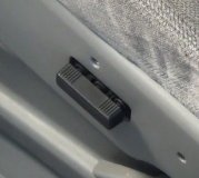
Digital readout gets garbled, or totally blank, or sometimes works normal. Indicates probably just a bad connection.
Previously i said it was the contacts on the blue connector. This is not the problem!
The "blue connector" fix did not last very long. It appears the only reason it worked at all is that it applied some pressure (temporarily) on the Digital Display module.
After much experimentation and testing, it appears the true culprit is the Digital Display module itself.
I believe there is a bad electrical connection somewhere within this module, or within its external connections.
Not likely that this module could be disassembled and fixed, so I just experimented with placing pressure in various places on the module.
I found that light pressure on the left side of the module produced the best outcome. You should experiment for the best location for pressure.
I simply stacked up a number of small duct tape strips on the left side of the module until that stack was about 1/4", such that when stalled, the Instrument Cluster Face Plate would constantly put a little pressure on the Digital Display module.
Obviously this requires removal and disassembling the Instrument Cluster. There are videos online to remove the Instrument Cluster.
Here’s the one I used:
https://youtu.be/G-OcWt_Rm3Y
To disassemble the Instrument Cluster, all you need is a flat blade screwdriver to unhook the plastic tabs around the front cover.
Now to get to the Digital Display module itself, the Instrument Cluster Face Plate must be removed.
Here where it gets tricky:
Unless you cut the Instrument Cluster Face Plate, the speedometer, tachometer, fuel gauge, and temp gauge needles must be removed.
These needles have been on for many years, and mine where tough to remove, especially the speedometer.
When I had everything back together, everything worked except the speedometer.
So, disassembled the Instrument Cluster again, and found that the pin on the speedometer stepper motor was very difficult to turn, while the other 3 stepper motor pins turned very easily.
With a small screwdriver, I was able to pop the back off the stepper motor and found that the plastic sleeve around the pin had expanded.
Turns out when I pulled off the speedometer needle originally, the pin on the stepper motor pulled partway thru its plastic sleeve, and actually expanded the plastic sleeve such that the sleeve was too tight for the motor to turn it.
So, I painstakingly filed the plastic sleeve down until it would turn appropriately within the stepper motor, and it now works.
Considering the tight tolerances within these tiny stepper motors, this speedometer fix might not last.
So if I were to do this again, I would neatly cut the Instrument Cluster Face Plate in half between the tachometer and speedometer.
This way you only need to remove the tachometer needle, and if that breaks, its just the tachometer.
I also recommend adding some layers of duct tape (and one piece of black electrical tape on top to match) to the Instrument Cluster Face Plate above the stacked up duct tape strips on the Digital Display module.
Enough layers such that the front cover of the Instrument Cluster rests on these layers.
That way if the Digital Display messes up again, you can just press on the front cover, and the pressure will transfer to the Digital Display module and hopefully straighten it out for a while.
See attached pictures of duct tape stack on Digital Display module, and duct tape stack (and electrical tape) on Instrument Cluster Face Plate.
Images (Click to make bigger)
Monday, June 15th, 2020 AT 2:00 PM


