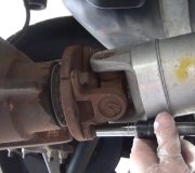
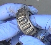
Check the actuator and motor movement.
ACTUATOR
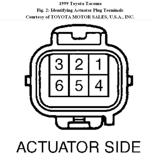
1. Using ohmmeter, measure resistance between terminals No. 2 and 3. Resistance should be.3-100 ohms. See Fig. 2.
2. Using ohmmeter, measure resistance between terminals No. 2 or 3 and chassis ground. Resistance should be greater than 500 k/ohms. If resistance values are not as specified, replace actuator assembly.
3. Check actuator limit switch continuity. Connect positive lead from battery to terminal No. 2 and negative lead to terminal No. 3. Connect positive lead from ohmmeter to terminal No. 5 and negative lead to terminal No. 4. Ensure continuity exists between terminals No. 4 and 5.
4. Connect positive lead from battery to terminal No. 3 and negative lead to terminal No. 2. Connect positive lead from ohmmeter to terminal No. 6 and negative lead to terminal No. 4. Ensure continuity exists between terminals No. 4 and 6. If continuity is not as specified, replace actuator assembly.
ACTUATOR MOTOR OPERATION
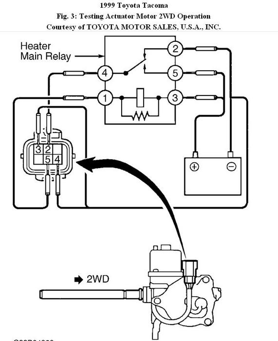
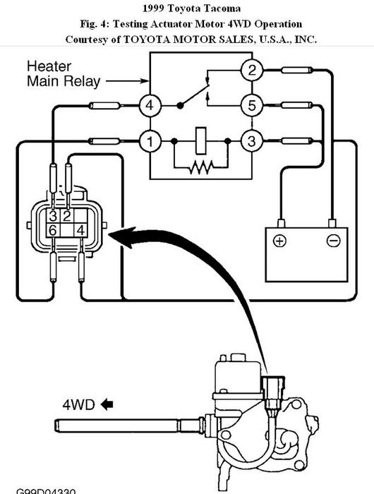
Connect heater main relay between actuator connector and battery. See
Fig. 3. Actuator shaft fork should move to 2WD position. Connect heater main relay between actuator connector and battery. See Fig. 4. Actuator shaft fork should move to 4WD position. If actuator does not operate as described, replace actuator.
Images (Click to make bigger)
Sunday, December 12th, 2010 AT 4:22 PM
