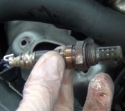
I believe you have replaced the wrong sensor.
Bank 2 refers to left cylinder bank, meaning driver side and is it is the one rear of left catalytic converter.
DTC P0161 : HEATED OXYGEN SENSOR (HO2S) NO. 2 BANK 2/HEATER CIRCUIT
NOTE:
ALWAYS inspect a faulty HO2S for contamination and correct cause before installing a new HO2S. Bank 2 refers to left cylinder bank.
Diagnostic Aids
An intermittent may be caused by a poor connection, rubbed through wire insulation or a broken wire inside insulation. Inspect harness connectors for backed out terminals, improper mating, broken locks, improperly formed or damaged terminals, poor terminal-to-wire connection, and damaged harness. If DTC cannot be duplicated,
check scan tool FAILURE RECORDS to determine mileage since last DTC was set.
1. Perform On-Board Diagnostic (OBD) System Check. Go to next step.
2. Allow engine to cool. Disconnect fuel pump relay. On 3.2L, connect fused jumper between fuel pump relay socket positive battery terminal No. 5 (White/Black wire) and relay wire that goes to fuel pump and HO2S fuses (Black/Red wire). On 3.5L, connect fused jumper between fuel pump relay socket positive battery terminal No. 4 (White wire) and relay wire that goes to fuel pump and HO2S fuses (Red wire). On all models, turn ignition off. Install scan tool. Turn ignition on. Observe HO2S No. 2, bank 2 parameter on scan tool for several minutes. If display is greater than 650 mV or less than 250 mV, check for an intermittent problem, see DIAGNOSTIC AIDS. If display is not greater
than 650 mV or less than 250 mV, go to next step.
3. Inspect HO2S heater fuse (20-amp) in engine compartment fuse box. If fuse is blown, check for short in circuit and replace fuse. Retest system. If fuse is okay, go to next step.
4. Turn ignition off. Raise and support vehicle. Disconnect HO2S No. 2, bank 2 harness connector. Turn ignition on. Connect test light between ground and ignition feed circuit (Red/Blue wire - 3.2L; Red/White wire - 3.5L) at connector (PCM side). If test light comes on, go to next step. If test light does not come on, go to step 7).
5. Connect test light between ignition feed circuit (Red/Blue wire -
3.2L; Red/White wire - 3.5L) and ground circuit (Black wire) at connector (PCM side). If test light comes on, go to next step. If test light does not come on, go to step 8).
6. Turn ignition off. Ensure HO2S No. 2 is cool. Measure resistance between ignition feed circuit (Red/Blue wire - 3.2L; Red/White wire - 3.5L) and heater ground circuit (Black wire) at HO2S No. 2 harness connector (sensor side). If resistance is 3-6 ohms, go to step 9). If resistance is not 3-6 ohms, go to step 10).
7. Repair open in HO2S No. 2 ignition feed circuit (Red/Blue wire -
3.2L; Red/White wire - 3.5L). Retest system.
8. Repair open in HO2S No. 2 ground circuit (Black wire). Retest system.
9. Check for poor connection at HO2S No. 2, bank 2 harness terminals. Repair as necessary. Retest system. If harness is okay, go to next step.
10. Check for poor connection at HO2S No. 2, bank 2 high or low circuit terminal connections at harness connector. Repair as necessary. Retest system. If connections are okay, go to next step.
11. Turn ignition off. Disconnect PCM harness connector terminals. Measure resistance of HO2S No. 2, bank 2 high and low signal circuits (White/Blue and Orange/Blue wires - 3.2L; Blue and Green wires -
3.5L) at PCM harness connector. If either circuit resistance is greater than 5 ohms, check for an open or poor connection. Repair as necessary. If wires are okay, go to next step.
12. Check for poor HO2S No. 2, bank 2 terminal connections at PCM. Repair as necessary. If connections are okay, replace HO2S No. 2, bank 2. Retest system.
Tuesday, August 23rd, 2011 AT 10:49 PM


