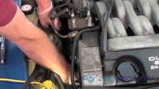
Removal
1. Remove� all� drive� belts.� Remove� crankshaft� pulley� and� water� pump� pulley.� Remove� upper� and� lower� timing� belt� covers, � noting� bolt� lengths� and� locations.
2. Turn� crankshaft� clockwise� and� align� timing� marks� so� No.� 1� cylinder� is� at� TDC.� Timing� marks� on� camshaft� sprockets� should� be� aligned� at� upper� surface� of� cylinder� head.� See Fig.� 1�.� Camshaft� sprocket� dowel� pins
should� face� upward.
CAUTION: DO� NOT� rotate� crankshaft� counterclockwise� (as� viewed� from� timing� belt� end� of� engine).� If� reusing� timing� belt, � mark� direction� of� belt� rotation� before
removing.
3. Remove� timing� belt� automatic� tensioner.� See Fig.� 2�.� Mark� timing� belt� to� indicate� original� direction� of� rotation.� Remove� timing� belt.
4. Remove� balance� shaft� access� plug� from� cylinder� block.� Insert� Phillips� screwdriver� to� block� left� balance� shaft.� See Fig.� 3�.� Balance� shaft� is� correctly� locked� in� place� if� screwdriver� can� be� inserted� at� least� 2.36"� (60
mm).� If� not, � rotate� oil� pump� sprocket� so� screwdriver� can� be� inserted� to� correct� depth.
5. Loosen� balance� shaft� belt� tensioner� bolt.� Remove� front� crankshaft� sprocket� and� flange.� Remove� balance� shaft� timing� belt.
Fig.� 1:� Aligning� Timing� Marks
Courtesy� of� HYUNDAI� MOTOR� CO.
Fig.� 2:� Exploded� View� Of� Timing� Belt� &� Related� Components
Courtesy� of� HYUNDAI� MOTOR� CO.
Fig.� 3:� Locking� Left� Balance� Shaft� In� Place
Courtesy� of� HYUNDAI� MOTOR� CO.
Install:
1. Align� timing� marks� on� balance� shaft� sprockets� with� timing� marks� on� engine� case.� Install� balance� shaft� timing� belt� and� crankshaft� flange.� Install� crankshaft� flange� in� correct� direction.� See Fig.� 5�.
2. Position� balance� shaft� tensioner� so� that� the� center� of� the� pulley� is� to� the� left� and� above� the� tensioner� bolt.� Hold� tensioner� tightly� against� belt.� Tighten� tensioner� pulley� bolt� without� letting� tensioner� rotate.
3. To� check� balance� shaft� belt� tension, � depress� belt� with� finger� midway� between� sprockets� (opposite� tensioner� pulley).� Deflection� should� be� between�.20 .29"� (57� mm).� If� not, � readjust� belt� tension.
4. Place� crankshaft� sprocket� on� crankshaft.� Tighten� bolt� to� specification.� See TORQUE� SPECIFICATIONS�.
5. Ensure� screwdriver� is� still� installed� through� left� side� of� cylinder� block� to� hold� balance� shaft� in� place.� Install� automatic� tensioner� on� engine� block� with� rod� locked� in� place.
6. Rotate� camshaft� sprockets� so� dowel� pins� face� upward� and� timing� marks� on� sprockets� align.� See Fig.� 1�.� Outer� marks� on� sprockets� should� be� aligned� with� cylinder� head� surface.
NOTE: The� same� camshaft� sprockets� are� installed� on� intake� and� exhaust� camshafts.� Timing� marks� are� correctly� aligned� when� dowel� pin� holes� are� facing� straight
up.
7. Align� crankshaft� sprocket� timing� marks� and� oil� pump� sprocket� timing� marks.� See Fig.� 1�.� Install� timing� belt� around� tensioner� pulley� and� crankshaft� sprocket.� Hold� timing� belt� on� tensioner� pulley� using� left� hand.
Pulling� belt� with� right� hand, � install� belt� around� oil� pump� sprocket.
8. Install� belt� around� idler� pulley.� Align� timing� mark� on� exhaust� camshaft� sprocket� with� top� of� cylinder� head.� Pulling� belt� with� both� hands, � install� it� around� exhaust� camshaft� sprocket.
9. Gently� raise� tensioner� pulley� so� belt� does� not� sag.� Position� timing� belt� tensioner� pin� holes� so� that� they� face� up.� Temporarily� tighten� center� bolt.� See Fig.� 6�.
0. To� adjust� belt� tension, � rotate� crankshaft� 1/4� turn� counterclockwise, � and� then� rotate� clockwise� until� No.� 1� cylinder� is� at� TDC.� Ensure� all� timing� marks� are� aligned.
1. Loosen� center� bolt� on� tensioner� pulley.� Note� location� of� pin� holes� in� tensioner� pulley.
2. Using� INCH lb.� Torque� wrench� and� Socket� Wrench� (09224 28100), � apply� a� torque� of� 22 24� INCH� lbs.� (2.6 2.8� N.M)� on� tensioner� pulley.� With� torque� applied� to� tensioner� pulley, � tighten� tensioner� pulley� center
bolt� to� specification.� See Fig.� 7�.� See TORQUE� SPECIFICATIONS�.
3. Install� Set� Screw� (09244 28000), � or� equivalent, � in� left� engine� support� bracket� until� set� screw� end� contacts� tensioner� arm.� Rotate� set� screw� further� until� locking� pin� can� be� removed� from� automatic� tensioner.� See
Fig.� 6�.� Remove� set� screw.
4. Rotate� crankshaft� clockwise� 2� complete� revolutions.� Allow� engine� to� sit� in� this� position� for� about� 15� minutes.� Measure� distance� between� tensioner� arm� and� automatic� tensioner� body.� Distance� should� be�.15
.18"� (3.8 4.5� mm).� See Fig.� 8�, � Dimension� "A".� If� distance� is� incorrect, � repeat� timing� belt� tensioning� procedure.� If� distance� is� okay, � go� to� step 17�.
5. If� distance� between� automatic� tensioner� and� tensioner� arm� cannot� be� measured� easily, � use� this� alternate� method.� Install� Set� Screw� (09244 28000)� until� it� contacts� tensioner� arm.
6. Rotate� set� screw� inward� while� counting� number� of� turns� until� tensioner� arm� contacts� automatic� tensioner� housing.� Turn� set� screw� 2� 1/2 3� turns� to� correctly� tension� belt.� Remove� set� screw.
7. Install� rubber� plug� in� rear� timing� belt� cover.� Install� timing� belt� covers.� Install� timing� belt� cover� bolts� in� correct� locations.� See Fig.� 9�.
8. To� complete� installation, � reverse� removal� procedure.� Apply� sealant� to� contact� areas� on� semi circular� packing� and� rocker� cover� before� installing.� Ensure� correct� bolts� are� installed� in� proper� location� in� timing� belt
covers.� Adjust� drive� belts� to� proper� tension. Pay attention to timing marks. And if your belt broke you have more than likely bent valves as this is not a fre spin engine. Alot of pics enclosed.
Images (Click to make bigger)
Tuesday, October 27th, 2020 AT 4:12 PM
(Merged)